2.17
Date Code 20050919
Instruction Manual
SEL-387-0, -5, -6 Relay
Installation
Circuit Board Configuration
Password and Breaker Jumpers
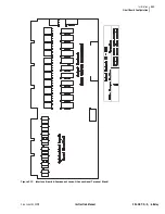
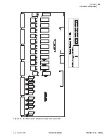
and note the password and breaker jumpers identified as
JMP6. To change these jumpers, remove the relay front panel and main board
according to the steps outlined previously in
.
Put password jumper JMP6A (left-most jumper) in place to disable serial port
and front-panel password protection. With the jumper removed, password
security is enabled. View or set the passwords with the
PASSWORD
command (see
Section 7: Serial Port Communications and Commands
Put breaker jumper JMP6B in place to enable the serial port commands
OPEN
,
CLOSE
, and
PULSE
. The relay ignores these commands while you
remove JMP6B. Use these commands primarily to assert output contacts for
circuit breaker control or testing purposes (see
).
Do not install jumpers in position JMP6C or JMP6D. If a jumper is in position
JMP6D and you lose dc power to the relay, the relay will power up in
SELBOOT when power is restored. The front panel will show
SELBOOT
and
then a warning to remove the jumper when you attempt serial port
communication.
EIA-232 Serial Port Jumpers
Refer to
. Jumpers JMP1 and JMP2 are toward the rear of the main
board, near the rear-panel EIA-232 serial communications ports. These
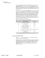
jumpers connect or disc5 Vdc to Pin 1 on the EIA-232 serial
communications
SERIAL PORTS 2
and
3
. SEL normally ships relays with these
jumpers removed (out of place) so that the +5 Vdc is not connected to Pin 1 on
the EIA-232 serial communications ports. JMP1 controls the +5 Vdc for
SERIAL PORT 3
, and JMP2 controls the +5 Vdc for
SERIAL PORT 2
(see
).
If these jumpers are installed, be certain not to short the power supply with an
incorrect communication cable. The +5 Vdc connections supply current as
high as 1 A.
Solder jumpers JMP3 and JMP4 allow connection of an IRIG-B source to
SERIAL PORT 2
. Removal of JMP3 and JMP4 will cause
SERIAL PORT 2
to no
longer accept an IRIG-B signal. The
SERIAL PORT 1
connector always accepts
an IRIG-B signal.
SERIAL PORT 2
and
SERIAL PORT 1
IRIG-B circuits are in
parallel; therefore, connect only one IRIG-B source at a time.
Condition of Acceptability for North American Product Safety
Compliance
To meet product safety compliance for end-use applications in North America,
use an external fuse rated 3 A or less in-line with the +5 Vdc source on pin 1.
SEL fiber-optic transceivers include a fuse that meets this requirement.
Other Jumpers
Additional main board jumpers JMP5A through JMP5D, located near JMP6,
are not functional in the SEL-387. Originally they were installed for
developmental testing purposes but are not used in the production version of
the relay. Jumpers must not be installed in any JMP5 position.
Summary of Contents for SEL-387-0
Page 10: ...This page intentionally left blank ...
Page 16: ...This page intentionally left blank ...
Page 56: ...This page intentionally left blank ...
Page 350: ...This page intentionally left blank ...
Page 388: ...This page intentionally left blank ...
Page 456: ...This page intentionally left blank ...
Page 494: ...This page intentionally left blank ...
Page 528: ...This page intentionally left blank ...

