background image

G.16

SEL-387-0, -5, -6 Relay

Instruction Manual

Date Code 20050919

Distributed Network Protocol

DNP3 Documentation

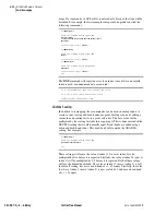
Control Relay Output Blocks (object 12, variation 1) are supported. The 
control relays correspond to the remote bits and other functions, as shown 
above. The Trip/Close bits take precedence over the control field. If either the 
Trip or Close bit is set, one of the other control field bits must be set as well. 
The control field is interpreted as follows:

If the Trip bit is set, a Latch Off operation is performed, and if the Close bit is 
set, a Latch On operation is performed on the specified index. The Status field 
is used exactly as defined. All other fields are ignored. A pulse operation 
asserts a point for a single processing interval. Caution should be exercised 
with multiple remote bit pulses in a single message (i.e., point count > 1), as 
this can result in some of the pulse commands being ignored and returning an 
already active status.

Analog Outputs (objects 40 and 41) are supported as defined by the preceding 
table. Flags returned with object 40 responses are always set to 0. The Control 
Status field of object 41 requests is ignored. If the value written to index 0 is 
outside of the range 1 through 6, the relay will not accept the value and will 
return a hardware error status.

Index

Close (0x4X) 

Trip (0x8X) 

Latch On (3)

Latch Off (4)

Pulse On (1) 

Pulse Off (2)

0–15

Set

Clear

Set

Clear

Pulse

Clear

16–23

Pulse

Do nothing

Pulse

Do nothing

Pulse

Do nothing

24

Pulse RB2

Pulse RB1

Pulse RB2

Pulse RB1

Pulse RB2

Pulse RB1

25

Pulse RB4

Pulse RB3

Pulse RB4

Pulse RB3

Pulse RB4

Pulse RB3

26

Pulse RB6

Pulse RB5

Pulse RB6

Pulse RB5

Pulse RB6

Pulse RB5

27

Pulse RB8

Pulse RB7

Pulse RB8

Pulse RB7

Pulse RB8

Pulse RB7

28

Pulse RB10

Pulse RB9

Pulse RB10

Pulse RB9

Pulse RB10

Pulse RB9

29

Pulse RB12

Pulse RB11

Pulse RB12

Pulse RB11

Pulse RB12

Pulse RB11

30

Pulse RB14

Pulse RB13

Pulse RB14

Pulse RB13

Pulse RB14

Pulse RB13

31

Pulse RB16

Pulse RB15

Pulse RB16

Pulse RB15

Pulse RB16

Pulse RB15

32

Pulse CC1

Pulse OC1

Pulse CC1

Pulse OC1

Pulse CC1

Pulse OC1

33

Pulse CC2

Pulse OC2

Pulse CC2

Pulse OC2

Pulse CC2

Pulse OC2

34

Pulse CC3

Pulse OC3

Pulse CC3

Pulse OC3

Pulse CC3

Pulse OC3

35

Pulse CC4

Pulse OC4

Pulse CC4

Pulse OC4

Pulse CC4

Pulse OC4

36–41

Pulse

Do nothing

Pulse

Do nothing

Pulse

Do nothing

Table G.7

SEL-387-5, -6 Relay Binary Input Lookup Table 

(Sheet 1 of 3)

Row

SEL-387 Relay Word Bits

Binary 

Input 
Point

2

50P11

50P11T

50P12

51P1

51P1T

51P1R

PDEM1

OCA

7–0

3

50A13

50B13

50C13

50P13

50A14

50B14

50C14

50P14

15–8

4

50N11

50N11T

50N12

51N1

51N1T

51N1R

NDEM1

OC1

23–16

5

50Q11

50Q11T

50Q12

51Q1

51Q1T

51Q1R

QDEM1

CC1

31–24

6

50P21

50P21T

50P22

51P2

51P2T

51P2R

PDEM2

OCB

39–32

7

50A23

50B23

50C23

50P23

50A24

50B24

50C24

50P24

47–40

8

50N21

50N21T

50N22

51N2

51N2T

51N2R

NDEM2

OC2

55–48

9

50Q21

50Q21T

50Q22

51Q2

51Q2T

51Q2R

QDEM2

CC2

63–56

Summary of Contents for SEL-387-0

Page 1: ...20050919 SEL 387 0 5 6 Relay Current Differential Overcurrent Relay Data Recorder Instruction Manual PM387 01 NB ...

Page 2: ...icant Se débarrasser des piles usagées suivant les instructions du fabricant ATTENTION La capacité en régime permanent des entrées de courant est 3 Inom Si un courant d essai dépassait cette valeur réduire la prise TAPn pour prévenir les dommages aux circuits d entrée ATTENTION La limite en régime permanent des entrées de courant est 3 Inom Pour ce test vous pourriez choisir de valeurs peu élevées...

Page 3: ... 7 Conventional Terminal Blocks 1 7 Plug In Connectors Connectorized 1 7 Specifications 1 8 Section 2 Installation Overview 2 1 Relay Mounting 2 2 Rack Mount 2 2 Panel Mount 2 2 Dimensions and Cutout 2 3 Rear Panel Connections 2 6 Terminal Block 2 6 Connectorized 2 6 Connections 2 10 Typical AC DC Connections 2 13 Circuit Board Configuration 2 15 Accessing the Relay Circuit Boards 2 15 Main Board ...

Page 4: ...trol Equation Settings SS1 through SS6 4 6 Operation of Serial Port GROUP Command and Front Panel GROUP Pushbutton 4 7 Relay Disabled Momentarily During Active Setting Group Change 4 7 Active Setting Group Switching Example 4 7 CHSG Relay Word Bit Asserts During Setting Group Changes 4 9 Active Setting Group Retained for Power Loss Settings Change 4 10 SELOGIC Control Equation Sets 1 Through 3 Var...

Page 5: ...tor 5 9 Instantaneous Battery Voltage Values 5 9 Undervoltage and Overvoltage Alarms 5 9 Detection of Voltage Dips in Event Reports 5 10 Breaker Monitor 5 11 Breaker Monitor Description and Initiation Setting 5 11 Breaker Wear Curve Description and Settings 5 12 Breaker Wear Example 5 14 Breaker Monitor Report Function BRE Command 5 14 Thermal Monitor SEL 387 6 Relay 5 16 Thermal Monitor Report Fu...

Page 6: ...9 Communications Ports 6 9 Default Settings 6 10 SEL 387 Default Settings 5 A 6 10 SEL 387 Default Settings 1 A 6 12 Settings Sheets 6 14 Settings Sheets Settings Sheets Example Section 7 Serial Port Communications and Commands Overview 7 1 Establish Communication 7 2 Software 7 2 Port Identification 7 2 Cables 7 2 SEL 387 to Computer 7 4 SEL 387 to Modem 7 5 SEL 387 to SEL Communications Processo...

Page 7: ...ettings 9 21 Retrieving SER Event Report Rows 9 21 Clearing SER Event Report Buffer 9 22 Section 10 Testing and Troubleshooting Overview 10 1 Testing Methods and Tools 10 2 Test Features Provided by the Relay 10 2 Low Level Test Interface 10 2 Test Methods 10 3 Acceptance Testing 10 5 Equipment Required 10 5 Initial Checkout 10 5 Power Supply 10 6 Serial Communications 10 6 Outputs 10 9 Inputs 10 ...

Page 8: ...A5CE Fast Operate D 10 A5E0 Fast Operate D 11 A5E3 Fast Operate D 12 A5CD Fast Operate D 12 A5ED Fast Operate D 12 A546 Temperature D 13 ID Command D 13 DNA Command D 13 BNA Command D 14 SNS Message D 14 Appendix E Compressed ASCII Commands Overview E 1 CASCII Command General Format E 2 SEL 387 0 5 Relay E 4 CASCII Command E 4 CBREAKER Command E 5 CEVENT Command E 5 CEVENT Winding Report Default E...

Page 9: ...ble Unsolicited Data Transfer F 3 0x02 Function Code Disable Unsolicited Data Transfer F 4 0x18 Function Unsolicited Sequence of Events Response F 4 Acknowledge Message F 5 Examples F 6 Notes F 7 Appendix G Distributed Network Protocol Overview G 1 Configuration G 2 Data Link Operation G 4 Data Access Method G 5 DNP3 Documentation G 6 Device Profile G 6 Object Table G 7 Data Map G 10 Relay Summary...

Page 10: ...This page intentionally left blank ...

Page 11: ...ial Port SET Commands 6 1 Table 6 2 SET Command Editing Keystrokes 6 3 Table 7 1 Serial Port Pin Definitions 7 2 Table 7 2 SEL 387 Communication Cable Numbers 7 3 Table 7 3 Serial Communications Port Pin Function Definitions 7 6 Table 7 4 MET Command Choices 7 22 Table 7 5 Editing Keys for SET Commands 7 27 Table 7 6 Settings for Each Communication Port 7 28 Table 7 7 TFE Command Choices 7 37 Tabl...

Page 12: ...ration Block D 3 Table D 5 A5D1 Fast Meter Data Block D 7 Table D 6 A5C2 A5C3 Demand Peak Demand Fast Meter Configuration Messages D 7 Table D 7 A5D2 A5D3 Demand Peak Demand Fast Meter Message D 10 Table D 8 A5CE Fast Operate Configuration Block D 10 Table D 9 A5E0 Fast Operate Remote Bit Control D 12 Table D 10 A5E3 Fast Operate Breaker Control D 12 Table D 11 A5CD Fast Operate Reset Definition B...

Page 13: ... 0 3 5 Figure 3 5 Differential Element Decision Logic 3 6 Figure 3 6 Differential Element Harmonic Blocking Logic 3 8 Figure 3 7 Differential Element 87BL1 Blocking Logic SEL 387 0 3 9 Figure 3 8 Differential Element 87BL1 Blocking Logic All But SEL 387 0 3 9 Figure 3 9 DC Blocking DCBL1 Logic All But SEL 387 0 3 10 Figure 3 10 Winding Connections Phase Shifts and Compensation Direction 3 20 Figur...

Page 14: ...cal Control Switch Configured as an ON OFF MOMENTARY Switch 8 11 Figure 8 5 METER Menu and Display Structure 8 26 Figure 8 6 EVENTS Display Structure 8 27 Figure 8 7 OTHER BKR Menu and Display Structure 8 28 Figure 8 8 SET Menu and Display Structure 8 29 Figure 9 1 Example Event Summary 9 4 Figure 9 2 Example Winding Event Report 9 6 Figure 9 3 Example Digital Event Report 9 8 Figure 9 4 Example D...

Page 15: ...re B 12 Example Filename Identifying Old Firmware Version B 10 Figure B 13 Downloading Old Firmware B 10 Figure B 14 Selecting New Firmware to Send to the Relay B 12 Figure B 15 Transferring New Firmware to the Relay B 12 Figure B 16 Preparing HyperTerminal for ID Command Display B 16 ...

Page 16: ...This page intentionally left blank ...

Page 17: ...ting the relay for such functions as control obtaining target information and obtaining metering information Section 8 Front Panel Interface Describes use of the front panel to perform the actions of serial port commands Section 5 Metering and Monitoring Explains how to retrieve such operations data as metering results dc battery status breaker wear through fault event data and relay status Sectio...

Page 18: ...ork Protocol Describes DNP3 protocol SEL 387 Relay Command Summary Summarizes the serial port commands fully described in Section 7 Page Numbering This manual shows page identifiers at the top of each page see the figure below Page Number Format The page number appears at the outside edge of each page a vertical bar separates the page number from the page title block The page numbers of the SEL 38...

Page 19: ...es included in these examples may not necessarily match those in the current version of your SEL 387 Example Description STATUS Commands typed at a command line interface on a PC Enter Single keystroke on a PC keyboard Ctrl D Multiple combination keystroke on a PC keyboard Start Settings PC software dialog boxes and menu selections The character indicates submenus CLOSE Relay front panel pushbutto...

Page 20: ...llows Indicates a potentially hazardous situation that if not avoided may result in minor or moderate injury or equipment damage CAUTION Indicates a potentially hazardous situation that if not avoided could result in death or serious injury WARNING Indicates an imminently hazardous situation that if not avoided will result in death or serious injury DANGER ...

Page 21: ...ettings permit you to use wye or delta connected current transformers with virtually any type of transformer winding connection The SEL 387 Differential Relay provides three differential elements with dual slope characteristics The second slope provides security against CT saturation for heavy through faults Be sure to conduct detailed analysis of CT performance under worst case saturation conditi...

Page 22: ...d SEL 387 6 Relay These relays also provide security against conditions that may cause relay misoperation resulting from both system and transformer events Use the fifth harmonic element to prevent relay misoperation during allowable overexcitation conditions Even harmonic elements second and fourth 3 51 P G 3 3 Combined 67G 1 3 Autotransformer 87 50 P G Q 51 P G Q Overcurrent Phase Ground Neg Seq...

Page 23: ...are used for the neutral CT only three of the winding inputs may be used for normal differential or overcurrent protection purposes Thermal Protection SEL 387 6 Relay The SEL 387 6 provides a thermal element based on advanced transformer models This thermal element calculates the operating temperature and insulation aging of mineral oil immersed power transformers being protected by the SEL 387 6 ...

Page 24: ... monitor to gather fault current level duration and date time for each through fault The monitor performs a simple I2t calculation and cumulatively stores calculation results for each phase Use these through fault event data to schedule proactive maintenance for transformers and to help justify possible system enhancements to mitigate through faults Programmable Optoisolated Inputs and Output Cont...

Page 25: ...urrent Protection Figure 1 3 Transformer and Low Voltage Bus Protection 3 3 3 3 52 52 52 52 51 P G Combined 87 50 P G Q 51 P G Q 50 P G Q 51 P G Q 50 P G Q 51 P G Q 50 P G Q 51 P G Q 51 P G Combined 3 3 3 3 52 4 52 5 52 3 52 1 52 2 87 50 P G Q 51 P G Q 50 P G Q 51 P G Q 50 P G Q 51 P G Q 50 P G Q 51 P G Q 51 P G Combined CT1 CT2B CT2A CT3 CT4 CT5 Low Voltage Bus ...

Page 26: ...lication Ideas Figure 1 4 Bus and Feeder Protection Figure 1 5 Unit Differential Protection 3 3 3 3 52 52 52 87 50 P G Q 51 P G Q 50 P G Q 51 P G Q 50 P G Q 51 P G Q 50 P G Q 51 P G Q 52 3 3 3 3 52 52 87 50 P G Q 51 P G Q 50 P G Q 51 P G Q 50 P G Q 51 P G Q 50 P G Q 51 P G Q SEL 300G0 SEL 300G1 52 ...

Page 27: ...l Terminal Blocks This model includes hardware that supports 12 current inputs 6 optoisolated inputs 7 programmable output contacts 1 alarm contact 3 EIA 232 ports 1 EIA 485 port and IRIG B time code It uses terminal blocks that support 6 ring terminals This robust package meets or exceeds numerous industry standard type tests This relay is available in a 3 50 2U or 5 25 3U rack mount package or 4...

Page 28: ...A continuous carry at 85 C 1 s Rating 50 A MOV Protection 330 Vdc 130 J Pickup Time 5 ms Dropout Time 8 ms typical Breaking Capacity 10000 operations 24 V 10 A L R 40 ms 48 V 10 A L R 40 ms 125 V 10 A L R 40 ms 250 V 10 A L R 20 ms Cyclic Capacity 4 cycles in 1 second followed by 2 minutes idle for thermal dissipation 24 V 10 A L R 40 ms 48 V 10 A L R 40 ms 125 V 10 A L R 40 ms 250 V 10 A L R 20 m...

Page 29: ...Electrostatic Discharge Test ESD IEC 60255 22 2 1996 IEC 61000 4 2 1995 Level 4 RFI and Interference Tests 1 MHz Burst Disturbance IEC 60255 22 1 1988 Class 3 Fast Transient Disturbance IEC 60255 22 4 1992 IEC 61000 4 4 1995 Level 4 Radiated EMI IEC 60255 22 3 1989 ENV 50140 1993 IEEE C37 90 2 1995 35 V m Surge Withstand IEEE C37 90 1 1989 3 0 kV oscillatory 5 0 kV fast transient Vibration and Sho...

Page 30: ...ycles Time Delay Accuracy 0 1 0 25 cycle Winding and Combined Current Time Overcurrent Elements Pickup Ranges A secondary 5 A Model 0 5 16 0 A 1 A Model 0 1 3 2 A Pickup Accuracies A secondary 5 A Model Steady State 3 0 10 A Transient 5 0 10 A 1 A Model Steady State 3 0 02 A Transient 5 0 02 A Note For transient 6 for negative sequence elements Curve U1 U S Moderately Inverse U2 U S Inverse U3 U S...

Page 31: ... Overview Design your installation using the mounting and connection information in this section Options include rack or panel mounting and terminal block or plug in connector Connectorized wiring This section also includes information on configuring the relay for your application ...

Page 32: ...t Panel Mount We also offer the SEL 387 in a panel mount version for a clean look Panel mount relays have sculpted front panel molding that covers all installation holes See Figure 2 1 Cut your panel and drill mounting holes according to the dimensions in Figure 2 1 Insert the relay into the cutout aligning four relay mounting studs on the rear of the relay front panel with the drilled holes in yo...

Page 33: ...2 3 Date Code 20050919 Instruction Manual SEL 387 0 5 6 Relay Installation Relay Mounting Dimensions and Cutout Figure 2 1 Relay Dimensions for Rack Mount and Panel Mount Models ...

Page 34: ...2 4 SEL 387 0 5 6 Relay Instruction Manual Date Code 20050919 Installation Relay Mounting Figure 2 2 Front Panel Drawings Models 0387x0xxxH and 0387x1xxxH ...

Page 35: ...2 5 Date Code 20050919 Instruction Manual SEL 387 0 5 6 Relay Installation Relay Mounting Figure 2 3 Front Panel Drawings Models 0387x0xxx3 and 0387x1xxx3 ...

Page 36: ...es maximum wiring flexibility for inputs and outputs and a quick disconnect voltage rated connector for voltage inputs The manufacturers of these connectors have tested them thoroughly and many industry applications have proven the performance of these connectors In addition we have tested these connectors thoroughly to ensure that they conform to our standards for protective relay applications Te...

Page 37: ...2 7 Date Code 20050919 Instruction Manual SEL 387 0 5 6 Relay Installation Rear Panel Connections Figure 2 4 Rear Panel Drawings Models 0387x0xxxxX and 0387x1xxxx2 ...

Page 38: ...2 8 SEL 387 0 5 6 Relay Instruction Manual Date Code 20050919 Installation Rear Panel Connections Figure 2 5 Rear Panel Drawings Models 0387x1xxxx4 and 0387x1xxxx6 ...

Page 39: ...2 9 Date Code 20050919 Instruction Manual SEL 387 0 5 6 Relay Installation Rear Panel Connections Figure 2 6 Rear Panel Drawings Models 0387xYxxxx6 and 0387xYxxxx2 ...

Page 40: ...RT 2 4 six position female plug in connectors for interface board output contacts OUT201 through OUT203 OUT204 through OUT206 OUT207 through OUT209 and OUT210 through OUT212 2 eight position female plug in connectors for interface board optoisolated inputs IN201 through IN204 and IN205 through IN208 Connections Frame Ground For safety and performance ground the relay chassis at terminal GND Z27 Co...

Page 41: ...lock version Figure 2 7 Standard Independent Output Contact Representation Connect output wiring to any of the additional output contacts OUT201 OUT212 you need for your application On the additional interface board you have the option of either standard or high current interrupting contacts High current interrupting contacts are polarity dependent A plus polarity mark next to the terminal requiri...

Page 42: ...des fiber optic links between devices for electrical isolation and long distance signal transmission Call the factory for further information on these products Clock Synchronization IRIG B Refer to Table 2 1 for a list of cables that you can purchase from SEL for various time synchronizing applications The SEL 387 accepts a demodulated IRIG B format signal for synchronizing an internal clock to so...

Page 43: ...is transformer has a neutral current CT connected to one of the three unused Winding 4 current inputs The Restricted Earth Fault REF protection function uses measured neutral current in conjunction with the residual current calculated from the Winding 1 CTs You can use the REF function only if CTs for the protected wye winding are themselves wye connected Delta connected CTs remove the zero sequen...

Page 44: ...t closes under conditions of complete relay power failure If breaker closing control were desired we would use the Trip Annunciator contact OUT105 as one of the three separate output contacts for connection to the breaker closing coils That is for this case the breaker trip and close functions together would require all seven standard output contacts Figure 2 9 Example DC Connections Basic Version...

Page 45: ...oard below the main board Step 5 Disconnect circuit board cables as necessary so you can remove the board and draw out tray you want a To remove the extra interface board first remove the main board b Remove ribbon cables by pushing the extraction ears away from the connector c Remove the six conductor power cable by grasping the wires near the connector and pulling away from the circuit board Ste...

Page 46: ...ct Jumper Note the locations of main board jumper JMP23 and output contact OUT107 in Figure 2 10 and refer to Table 2 2 to understand the relationship between the jumper and output contact The jumper JMP23 controls the operation of output contact OUT107 JMP23 provides the option of a second alarm output contact by changing the signal that drives output contact OUT107 If jumper JMP23 is installed o...

Page 47: ...r of the main board near the rear panel EIA 232 serial communications ports These jumpers connect or disconnect 5 Vdc to Pin 1 on the EIA 232 serial communications SERIAL PORTS 2 and 3 SEL normally ships relays with these jumpers removed out of place so that the 5 Vdc is not connected to Pin 1 on the EIA 232 serial communications ports JMP1 controls the 5 Vdc for SERIAL PORT 3 and JMP2 controls th...

Page 48: ...ery Follow the instructions previously described in Accessing the Relay Circuit Boards on page 2 15 to remove the relay main board Remove the battery from beneath the clip and install a new one The positive side of the battery faces up Reassemble the relay as described in Accessing the Relay Circuit Boards Set the relay date and time via serial communications port or front panel see Section 7 Seri...

Page 49: ...erface Board 2 Interface Board 4 and Interface Board 6 conventional terminal block respectively Figure 2 14 and Figure 2 15 show the layout of Interface Board 2 and Interface Board 6 Connectorized respectively The only difference between the two is the row of electronic components that form the interruption circuits of the high current interrupting contacts on Interface Board 6 ...

Page 50: ...2 20 SEL 387 0 5 6 Relay Instruction Manual Date Code 20050919 Installation Circuit Board Configuration Figure 2 10 Main Board Jumpers Connections and Battery Locations ...

Page 51: ...2 21 Date Code 20050919 Instruction Manual SEL 387 0 5 6 Relay Installation Circuit Board Configuration Figure 2 11 Interface Board 2 Component Layout Conventional Terminal Block ...

Page 52: ...2 22 SEL 387 0 5 6 Relay Instruction Manual Date Code 20050919 Installation Circuit Board Configuration Figure 2 12 Interface Board 4 Component Layout Conventional Terminal Block ...

Page 53: ...2 23 Date Code 20050919 Instruction Manual SEL 387 0 5 6 Relay Installation Circuit Board Configuration Figure 2 13 Interface Board 6 Component Layout Conventional Terminal Block ...

Page 54: ...2 24 SEL 387 0 5 6 Relay Instruction Manual Date Code 20050919 Installation Circuit Board Configuration Figure 2 14 Interface Board 2 Component Layout Connectorized ...

Page 55: ...2 25 Date Code 20050919 Instruction Manual SEL 387 0 5 6 Relay Installation Circuit Board Configuration Figure 2 15 Interface Board 6 Component Layout Connectorized ...

Page 56: ...This page intentionally left blank ...

Page 57: ...ion describes general applications and operating characteristics for the current differential restricted earth fault REF thermal and overcurrent protection elements The section also contains application guidelines for the differential and thermal elements and setting calculation information for the differential elements and restricted earth fault elements ...

Page 58: ...ses a characteristic such as that in Figure 3 1 You can set the characteristic as either a single slope percentage differential characteristic or as a dual slope variable percentage differential characteristic Tripping occurs if the Operate quantity is greater than the curve value for the particular restraint quantity A minimum pickup level for the Operate quantity must also be satisfied The four ...

Page 59: ...ment for Winding 1 I1W1C1 I2W1C1 and I3W1C1 are the fundamental frequency A phase B phase and C phase compensated currents for Winding 1 Similarly I1W1C2 I2W1C2 and I3W1C2 are the second harmonic compensated currents for Winding 1 The dc fourth harmonic and fifth harmonic compensated currents use similar names The I1 compensated currents are used with differential element 87 1 I2 with element 87 2...

Page 60: ...ult Thermal and Overcurrent Elements Differential Element Figure 3 3 Differential Element 87 1 Quantities SEL 387 0 IOP1 E87W1 I1W1C1 I1W3C1 I1W2C1 I1W4C1 E87W2 E87W3 E87W4 Σ ΣI1WnC1 E87W1 I1W1C2 I1W3C2 I1W2C2 I1W4C2 E87W2 E87W3 E87W4 IRT1 I1HB2 Σ Σ ΣI1WnC2 I1W1C1 I1W2C1 I1W3C1 I1W4C1 100 PCT2 2 ...

Page 61: ... windings while maintaining security for inrush and through fault conditions Operating current elements 87On 87O1 87O2 87O3 are provided for testing purposes Restrained elements 87R1 87R2 and 87R3 determine whether the IOP quantity is greater than the restraint quantity using the differential characteristic shown in Figure 3 1 Set HRSTR Y harmonic restraint all but SEL 387 0 to modify this charact...

Page 62: ...TR Y if your practices require independent harmonic restraint This feature automatically disables common harmonic blocking IHBL Y It also disables second and fourth harmonic blocking since it adds the second and fourth harmonic quantities IHRTn to the differential characteristic restraint quantity see Figure 3 4 and Figure 3 5 Blocking features are discussed in more detail later in this section Fo...

Page 63: ...e the default values for these settings to provide secure differential element operation for inrush conditions Blocking While the restrained differential elements are making decisions a parallel blocking decision process occurs regarding the magnitudes of specific harmonics in the IOP quantities Common Cross or Independent Blocking Use common or independent blocking elements 87BL1 87BL2 and 87BL3 ...

Page 64: ...ich drives contact OUT104 OUT104 connects to an 86 lockout device which trips all breakers via multiple sets of contacts Harmonic Blocking Figure 3 7 SEL 387 0 and Figure 3 8 all but SEL 387 0 show how the 87BL1 blocking element will pick up if the second fourth or fifth harmonic operating current as a percentage of fundamental operating current is above the 2PCT 4PCT or 5PCT setting threshold res...

Page 65: ...igure 3 8 DCBL is available as a Relay Word bit but elements DCBL1 DBL2 and DCBL3 are not The dc ratio blocking feature applies to inrush cases with little harmonic content but a high dc offset The measurement principle is that of wave shape recognition distinguishing between the time constants for inrush current that typically are longer than the time constants for an internal fault _ I1HB2 I1HB5...

Page 66: ... SEL 387 0 selecting Y1 makes the fourth harmonic PCT4 dc ratio blocking DCRB and harmonic restraint HRSTR settings available This is the only difference between Y and Y1 selection CT Connection W1CT W4CT Range D Y To perform calculations for TAPn values the relay uses information on whether the CTs are connected in delta D or wye Y for each winding If the CTs are connected in delta the relay rais...

Page 67: ...he secondary currents for the differential calculation Connection Compensation W1CTC W4CTC Range 0 1 12 These settings define the amount of compensation the relay applies to each set of winding currents to properly account for phase shifts in transformer winding connections and CT connections For example this correction is needed if both wye and delta power transformer windings are present but all...

Page 68: ...very heavy current levels that clearly indicate an internal fault Set the pickup level U87P to about 10 times tap The unrestrained differential element only responds to the fundamental frequency component of the differential operating current It is unaffected by the SLP1 SLP2 IRS1 PCT2 PCT5 or IHBL settings Thus you must set the element pickup level high enough so as not to react to large inrush c...

Page 69: ...t the relay to block the percentage restrained differential element if the ratio of fourth harmonic current to fundamental current IF4 IF1 is greater than the PCT4 setting When using harmonic restraint HRSTR Y use the PCT4 setting to scale the amount of fourth harmonic content that will be added to the restraint slope characteristic The larger the PCT4 setting the smaller the increase on the restr...

Page 70: ...rrents during transformer energization Choose between harmonic blocking and harmonic restraint Harmonic blocking treats the second and fourth harmonics independently and blocks the relay when the second or fourth harmonic content harmonic current as a percentage of the fundamental current exceeds the PCT2 or PCT4 setting respectively For example assume the following PCT2 PCT4 20 percent and the ha...

Page 71: ...7 performs harmonic blocking in two ways 1 Independent Harmonic Blocking IHBL Y blocks the percentage differential element for a particular phase if the harmonic second or fifth in that phase exceeds the block threshold No blocking occurs on other differential elements 2 Common Harmonic Blocking IHBL N blocks all of the percentage differential elements if the harmonic magnitude of any one phase is...

Page 72: ...A RTD Modules total of 24 RTD inputs Configure the SEL 387 and SEL 2600A communication with the port setting SET P n n 1 2 3 or 4 Temperature Preference TMPREFA TMPREFB Range C F Located under the Global settings TMPREFA TMPREFB select the preferred temperature units C for Celsius or F for Fahrenheit The relay automatically recalculates all 49 element temperature values The SEL 387 can report a di...

Page 73: ... Compensation The general expression for current compensation is as follows Equation 3 4 Setting WnCTC m specifies which CTC m matrix the relay is to use The setting values are 0 1 2 11 12 These are discrete values m can assume in CTC m the values physically represent the m number of increments of 30 degrees that a balanced set of currents with ABC phase rotation will be rotated in a counterclockw...

Page 74: ...Wn The 1 setting performs a 30 degree compensation in the counterclockwise direction as would a delta CT connection of type DAB 30 degree leading The name for this connection comes from the fact that the polarity end of the A phase CT connects to the nonpolarity end of the B phase CT and so on in forming the delta Thus for WnCTC 1 the relay uses the following CTC m matrix Equation 3 6 that is Equa...

Page 75: ... 11 We could use this type of compensation in applications having wye connected transformer windings no phase shift with wye CT connections for each winding Using WnCTC 12 for each winding removes zero sequence components just as connection of the CTs in delta would do but without producing a phase shift One might also use WnCTC 1 or 11 for this same application yielding compensation similar to th...

Page 76: ...ete knowledge of the transformer winding connections and phase relationships the CT connections and the system phase rotation ABC or ACB The following brief review discusses the nature of various connections their phase shifts and the reference motion for selecting WnCTC based on system phase rotation Winding Connection Review Figure 3 10 shows the three basic winding connections consisting of a w...

Page 77: ...ection the line currents from the A B and C line terminals are respectively A C B A and C B in terms of the winding currents The phase shift produced by each physical type of delta depends on the system phase rotation In the ABC phase rotation B lags A by 120 degrees and C leads A by 120 degrees The DAB connection line current at terminal A is A B which in this case is a phasor that leads A windin...

Page 78: ...he relay currents to prevent false differential tripping on external ground faults All non zero values of WnCTC remove zero sequence current EXAMPLE 3 1 Example 1 for WnCTC Selection Figure 3 11 illustrates the first example This is a three winding transformer with a DAB delta primary and two lower voltage secondaries connected in grounded wye Two windings have wye connected CTs The higher voltage...

Page 79: ...we need make no adjustment for the 24 9 kV winding either Therefore the setting is W2CTC 0 As mentioned earlier these two windings represent a classical DABY application We can see this from the fact that the WnCTC setting is zero for both windings The CT connections themselves perform exactly the right correction without additional help from the relay The final winding inputs still reside at the ...

Page 80: ...ection because they both have wye connected CTs Winding 3 has DAC delta connected CTs and needs adjustment Refer to Figure 3 10 and note that the DAC connection produces a 30 degree shift in the CW direction for ABC phase rotation In the second line under the transformer drawings Figure 3 12 indicates this adjustment as a rotation of the Winding 3 direction from the 4 o clock to the 5 o clock posi...

Page 81: ...nt TAP The relay uses a standard equation to set TAPn based on settings entered for the particular winding n denotes the winding number Equation 3 12 The relay calculates TAPn with the following limitations The tap settings are within the range 0 1 IN and 31 IN The ratio TAPMAX TAPMIN 7 5 Restrained Element Operating Current Pickup The O87P setting range is 0 1 to 1 0 we suggest an O87P setting of...

Page 82: ...roves sensitivity in the region where CT error is small and increases security in the high current region where CT error is great We must define both slopes as well as the slope 1 limit or crossover point IRS1 If we assume CT error to be only 1 percent we can set SLP1 at about 25 percent A good choice for IRS1 is about 3 0 per unit of tap while the SLP2 setting should probably be in the 50 percent...

Page 83: ...p This alarm indicates that the rated transformer excitation current is exceeded At full load a TH5P setting of 0 1 corresponds to 10 percent of the fundamental current A delay TH5D that can be set by the user prevents the relay from indicating transient presence of fifth harmonic currents You may consider triggering an event report if transformer excitation current exceeds the fifth harmonic thre...

Page 84: ...rminals for the differential zone make the first settings as follows E87W1 Y E87W2 Y E87W3 Y These settings enable Windings 1 2 and 3 leaving Winding 4 available for stand alone overcurrent duty Step 2 Select settings for the current transformer connection and ratio for each winding All CTs connect in wye The ratios are equal to primary current divided by secondary current The settings are as foll...

Page 85: ...tages are in units of kV For this example we enter the following values VWDG1 230 VWDG2 138 VWDG3 13 8 The relay now calculates each tap current using the formula stated previously Equation 3 16 Thus we have the following Equation 3 17 Equation 3 18 Equation 3 19 The relay calculates these taps automatically if MVA is given If MVA is set to OFF the user must calculate the taps and enter them indiv...

Page 86: ...he least tap In this case O87PMIN 0 1 IN TAPMIN 0 5 1 74 0 287 Therefore the O87P setting of 0 3 is valid The differential unit settings are complete for this specific application At this point you can also choose to set backup overcurrent elements which we discuss at the end of this section Application Guideline It is vital that you select adequate current transformers for a transformer different...

Page 87: ...Ts IREL equals ILS For delta connected CTs IREL equals 3 ILS Select the nearest standard ratio such that IREL is between 0 1 IN and 1 0 IN A secondary Step 4 The SEL 387 calculates settings TAP1 through TAP4 if the ratio TAPMAX TAPMIN is less than or equal to 7 5 When the relay calculates the tap settings it reduces CT mismatch to less than 1 percent Allowable tap settings are in the range 0 1 31 ...

Page 88: ...ripping You can apply REF to a single wye winding in a transformer or to an entire autotransformer winding with as many as three sets of line end CT inputs The neutral CT connects to one of the three current inputs for Winding 4 IAW4 IBW4 or ICW4 leaving only three three phase winding inputs for normal differential or overcurrent protection purposes Figure 3 13 shows the REF simplified enable bloc...

Page 89: ... AND gate at left center in Figure 3 14 asserts This will occur if the two Relay Word bits 32IE and 50GC assert _ _ _ _ _ _ 50GP 32IOP 1 12 123 32IOP 2 12 123 23 32IOP 3 123 23 IRW4 _ 50G4 Relay Word bit CTR1 CTR4 CTR2 CTR4 CTR3 CTR4 IRW1 IRW2 IRW3 32IOP 1 12 123 32IOP 2 12 123 23 32IOP 3 123 23 32IE CTS E32I SELOGIC control equation _ 50GC Relay Word Bits 50GP 0 8 a0 I1W1 a0 I1W2 a0 I1W3 I0W2 I0W...

Page 90: ...ty for very small currents or for an angle very near 90 or 90 degrees If the 32I output exceeds the threshold test it then must persist for at least 1 5 cycles before the Relay Word bit 32IF forward or 32IR reverse asserts Assertion of 32IF constitutes a decision to trip by the REF function A second path can also assert the 32IF bit This path comes from the two position AND gate at the top right o...

Page 91: ... 50 in 0 01 steps For the relay to enable REF the zero sequence current at Winding n must be greater than a0 times the positive sequence current at that input or I0Wn a0 I1Wn This supervision provides security against false I0 that can occur because of CT saturation during heavy three phase faults Residual Current Sensitivity Threshold 50GP Range 1 A 0 05 3 A in 0 01 A steps 5 A 0 25 15 00 A in 0 ...

Page 92: ... input connected to the Winding 4 input of the relay as it must be for every case where REF protection is to be used If you want to protect an autotransformer set 32IOP at 12 and connect the primary and secondary side CTs to relay winding inputs 1 and 2 You could also use this setting for the single winding mentioned above if that winding had two breakers and two sets of CTs at the line end You wo...

Page 93: ... three ABC inputs e g IBW4 so the residual current for input 4 would be IRW4 0 IBW4 0 IBW4 Residual Current Sensitivity Threshold The second criterion of 50GP relates to the relative sensitivity of the winding CTs compared to the neutral CT Use the following equation to determine the minimum second criterion for 50GP Equation 3 20 where CTR4 is the neutral CT ratio and CTRmax is the greatest CT ra...

Page 94: ...L 387 thermal element compares top oil ΘTO and winding hot spot ΘH temperatures against thresholds beyond which a Relay Word bit will assert You can use these bits to alarm for overheating of the transformer Figure 3 17 Top oil temperature is a calculation of the transformer oil temperature while hot spot temperature is a calculation of the hottest point on the transformer winding The thermal elem...

Page 95: ...mperature to calculate the hot spot temperature The ambient temperature is reported in the thermal event reports For a single tank three phase transformer you will have as many as two thermal inputs the ambient temperature input and the top oil input For independent single phase transformers normally you will have as many as four thermal inputs an ambient temperature input and a top oil input for ...

Page 96: ...ent temperature according to the following Equation 3 27 where ΘH U the ultimate hot spot rise over top oil temperature for any load C ΘH i initial hot spot rise over top oil temperature at the start time of the interval C Ths thermal time constant of hot spot in hours set from Table 3 3 t one minute temperature data acquisition interval where K load expressed in per unit of transformer nameplate ...

Page 97: ...ure according to the following Equation 3 31 The relay has no measured ambient temperature input so you must select an ambient temperature setting DTMP for the thermal element calculation of top oil temperature as follows Equation 3 32 Top Oil Temperature Comparison to Indicate Cooling System Efficiency With measured top oil temperatures available top oil temperatures are also calculated using mea...

Page 98: ...o 0 Insulation Loss of Life Insulation Aging Acceleration Factor The relay thermal element uses the hot spot temperature to calculate an insulation aging acceleration factor FAA which indicates how fast the transformer insulation is aging The relay calculates the insulation aging acceleration factor FAA for each time interval t as follows Equation 3 33 Daily Rate of Loss of Life The relay calculat...

Page 99: ...L value at midnight each day You can use the THE P command to load an initial value of TLOL into the relay Estimated Time to Assert TLL Alarm Estimated time to assert TLL bit Equation 3 39 where FEQA equivalent insulation aging factor for a total time period n index of the time interval t N total number of time intervals for the time period FAAn insulation aging acceleration factor for the time in...

Page 100: ...hich of the four windings are in use For a two winding power transformer current transformers located on either the high voltage or low voltage side would provide the correct current values You can apply the thermal element on a three or four winding power transformer provided that the TMWDG setting represents the total current in or out Winding LL Voltage VWDG Range 1 1000 kV in 0 01 kV steps Set...

Page 101: ...t each is operating at the same cooling stage and the thermal constants are set identically Winding Temp Ambient Temp THwr Range 65 55 Rated winding rise over ambient temperature is the difference in degrees Celsius of the winding temperature of a transformer above the ambient temperature The actual winding temperature will be between the top oil and hot spot temperature Most power transformers ma...

Page 102: ...e thermal element calculations will use the DTMP setting should the ambient temperature input not function on relay power up If your data acquisition system cannot measure ambient temperature then the thermal element calculations always use the DTMP value The DTMP setting units are degrees Celsius Transformer De Energized TRDE Transformer heating consists of heating resulting from transformer loss...

Page 103: ...emperature 1 OIL2 top oil temperature 2 and OIL3 top oil temperature 3 If NTHM is set to 0 the relay assumes that it is not receiving any temperature inputs and will use only currents for its calculations The COMFLG bit is cleared when NTHM is set to 0 Ambient Temperature Input AMB SEL 387 6 Relays With Firmware Versions R606 and Later Range THM1 THM4 RTD1A RTD12A RTD1B RTD12B This setting assigns...

Page 104: ...ues exceeds a limit The thermal report will show which transformer exceeded the limits Hot Spot Temperature Limit HST1 HST2 Range 80 to 300 C in 1 C steps One of the outputs the thermal element provides is hot spot temperature HST1 and HST2 determine limits for hot spot temperature If the hot spot temperature exceeds one of these limits the corresponding HS1 or HS2 bit asserts Using SELOGIC contro...

Page 105: ...loss of transformer insulation life as a percentage of normal expected transformer insulation life TLOLL determines a limit for total loss of life If the total loss of life exceeds the limit a TLL bit asserts Using SELOGIC control equations you can configure the TLL bit to close an alarm contact With XTYPE 1 and aging acceleration factors being calculated for each of the three single phase transfo...

Page 106: ...uring a load change The winding time constant may be estimated from the resistance cooling curve during thermal tests or calculated by the manufacturer using the mass of the conductor materials Constant to Calculate FAA BFFAx Range 0 100000 in steps of 1 IEEE C57 91 1995 section 5 2 states that B BFFA is an empirical constant equal to 15000 Table 3 3 lists this value as the default You can select ...

Page 107: ...he following equation Equation 3 40 Table 3 3 lists default values The setting range for THgr is 0 to 100 C Ratio Losses RATLxy Range 0 1 100 in 0 1 steps RATL is the ratio of load loss at rated load to no load loss The default values listed in Table 3 3 are from IEEE C57 92 1981 Tables 2 and 4 If specific values for a particular transformer are known you can enter values from within a range of 0 ...

Page 108: ...directly with the SEL 2600A for gathering temperature readings some applications may use the SEL 2030 communications processor for retrieving the temperature data from the SEL 2600A The SEL 387 6 obtains temperature information via one of its serial ports The relay may receive data from as many as four temperature transducers a single ambient temperature transducer and one transducer for top oil t...

Page 109: ...lay Thermal Element for information about how to set the SEL communications processor to communicate with the SEL 2600A RTD Module and the SEL 387 6 Figure 3 19 Example System Block Diagram SEL 2600A or PLC SEL Communications Processor SEL 387 6 SEL Fast Messaging Temperature Inputs Power Transformer Station Computer Modbus SEL Fast Messaging or ASCII protocol ...

Page 110: ...rovide output information per phase and through an OR gate assert a Relay Word bit if any one of the three phases asserts These two elements primarily provide level detection for applications such as trip unlatch logic or phase identification In addition to the 11 overcurrent elements there are two sets of inverse time overcurrent elements that use combined currents from two windings These phase a...

Page 111: ...the 50Pn2 element The 50Pn2 element logic compares magnitudes of phase input currents IAWn IBWn and ICWn to pickup setting 50Pn2P If one or more current magnitudes exceed the pickup level a logic 1 asserts at one input to the AND gate The torque control SELOGIC control equation 50Pn2TC determines the other AND input If 50Pn2TC is true Relay Word bit 50Pn2 asserts Figure 3 21 50Pn2 Phase Instantane...

Page 112: ... pickup and the reset setting 51PnRS defines whether the curve resets slowly like an electromechanical disk or instantaneously when current drops below pickup The phase inverse time curve looks at all three phase current magnitudes and times on the basis of the greatest current of the three It updates this maximum phase current selection every quarter cycle If the curve times out Relay Word bit 51...

Page 113: ...ut delay along with 50Qn1T if it has asserted 50Nn1 Residual Definite Time Element The 50Nn1 element logic compares the magnitude of the calculated residual current IRWn to the pickup setting 50Nn1P If the calculated residual current magnitude exceeds the pickup level a logical 1 asserts at one input to the AND gate at the center The torque control SELOGIC control equation 50Nn1TC determines the o...

Page 114: ...he calculated negative sequence current 3I2Wn to the pickup setting 51QnP If the calculated negative sequence current exceeds the pickup level a logical 1 asserts at one input to the AND gate at the center The torque control SELOGIC control equation 51QnTC determines the other AND input If 51QnTC is true Relay Word bit 51Pn asserts and the inverse curve begins timing As with phase inverse time ele...

Page 115: ...on 51NnTD for the time dial and 51NnRS for the curve reset Curve time out causes Relay Word bit 51NnT to assert When the current drops below pickup 51Nn deasserts and the element resets according to the setting for 51NnRS At the completion of the reset Relay Word bit 51NnR asserts This bit normally is at logic state 1 when the element is at rest during normal system operation You can use the TAR c...

Page 116: ...ned Overcurrent Example 51PC1 and 51NC1 Element Figure 3 28 shows the logic for the inverse time combined overcurrent elements 51PC1 and 51NC1 1200 A 3800 A CT4 CT3 SEL 387 CB4 CB3 W1 2500 A 1300 A CT Equivalent 1 and 2 CT Equivalent 3 and 4 W3 and W4 Combination Windings 3 and 4 W1 and W2 Combination Windings 1 and 2 3800 A 1200 A 500 A 700 A CT1 CT2 CB1 CB2 W2 W3 W4 ...

Page 117: ...The following example illustrates the equivalent operation on the primary quantities entering the CTs Assume CTR1 600 5 120 CTR2 2000 5 400 InW1 2000 A primary InW2 1000 A primary Pickup 8000 A primary where n Phase A Phase B or Phase C Then converting the observed primary values to secondary values we have Equation 3 43 _ 51PC1 Pickup Curve Type Time Dial 51PC1 Wdg 1 and Wdg 2 Phase Inverse Time ...

Page 118: ...pickup setting 51PC1C for the particular curve equation 51PC1TD for the time dial and 51PC1RS for the curve reset Curve time out causes the Relay Word bit 51PC1T to assert When the current drops below pickup 51PC1 deasserts and the element resets according to the setting 51PC1RS At the completion of reset Relay Word bit 51PC1R asserts This bit normally is at logic state 1 when the element is at re...

Page 119: ... as the common base Equation 3 50 The combined secondary current value is less than the 51NC1P setting so 51NC1 does not assert For CTR1 CTR2 the relay performs the following operation on the secondary quantities it receives from the CTs Equation 3 51 defines a vector quantity Primary Currents IAW1 3000 2 A IAW2 1545 3 A IBW1 3010 122 A IBW2 1480 118 A ICW1 2950 117 A ICW2 1505 124 A Secondary Cur...

Page 120: ...ve equation 51NC1TD defines the time dial and 51NC1RS determines how the curve resets Curve time out causes the Relay Word bit 51NC1T to assert When the current drops below pickup 51NC1 deasserts and the element resets according to the setting 51NC1RS At the completion of the reset Relay Word bit 51NC1R asserts This bit normally will be at logic state 1 when the element is at rest during normal sy...

Page 121: ...les EOCn Range Y N Set EOC1 Y to enable overcurrent elements and demand thresholds for Winding 1 The operation is identical for the other three windings The relay default is for Winding 1 3 overcurrent elements and demand thresholds to be enabled while Winding 4 overcurrent elements and demand thresholds are disabled EOC4 N NOTE These two overcurrent elements should not be used if the REF function...

Page 122: ...ime Element Pickups 51PnP 51QnP 51NnP 51PCmP 51NCmP Range 1 A OFF 0 1 3 2 A secondary in 0 01 A steps 5 A OFF 0 5 16 A secondary in 0 01 A steps The pickup setting acts as a horizontal scaling factor for an inverse time curve because the curve formula uses current multiple of pickup as an input Set pickups and the following three settings defining the time overcurrent curve to fit the practices of...

Page 123: ...rer for specific transformer designs You can consult several references including the IEEE C37 91 Guide for Protective Relay Applications to Power Transformers that provide generic through current limitations for various classes of transformers Set the SEL 387 instantaneous overcurrent elements to detect high current faults within the transformer differential protection zone Use definite time and ...

Page 124: ...ttings and characteristics for the applied overcurrent protection Overcurrent Element Operating Quantities The SEL 387 phase overcurrent elements respond to the maximum phase current magnitude Ip where Ip is the largest value of Ia Ib and Ic Set phase overcurrent element pickup settings above the highest expected load current to avoid tripping on normal load current You can set the pickup lower if...

Page 125: ... define Pickup current in secondary amperes Operating time curve Operating time dial Element reset characteristic Element external torque control To disable a time overcurrent element set that element pickup setting OFF When the pickup setting is OFF the relay disables the element and you are not required to enter any remaining settings associated with the element The residual overcurrent elements...

Page 126: ...s and Definite Time Element Pickup and Time Delay Settings Use the instantaneous overcurrent elements to provide fast tripping for heavy internal transformer faults Set the element pickup settings high enough to prevent tripping for faults outside the protection zone Both definite time and instantaneous phase overcurrent elements are sensitive to load but should based on other setting constraints ...

Page 127: ...tively both using the U2 or U S Inverse curve on Time Dial 3 with electromechanical reset characteristics One of the phase instantaneous elements 50P13 is set very low at 0 5 A along with 50P23 and 50P33 on the other two windings These elements are employed in a supervisory mode for the Unlatch Trip function effectively defining when the breaker has opened by the dropping of phase current below th...

Page 128: ...eset setting TD Time dial setting M Applied multiples of pickup current for operating time Tp M 1 for reset time TR M 1 Table 3 5 Equations Associated with U S Curves Curve Type Operating Time Reset Time Figure U1 Moderately Inverse Figure 3 30 U2 Inverse Figure 3 31 U3 Very Inverse Figure 3 32 U4 Extremely Inverse Figure 3 33 U5 Short Time Inverse Figure 3 34 Table 3 6 Equations Associated with I...

Page 129: ...ed with IEC Curves Sheet 2 of 2 Curve Type Operating Time Reset Time Figure Tp TD 120 M 1 TR TD 120 1 M Tp TD 0 05 M 0 04 1 TR TD 4 85 1 M 2 0 50 6 00 5 00 4 00 3 00 2 00 1 00 15 00 12 00 10 00 8 00 01 5 6 7 8 9 1 02 03 04 05 09 07 06 08 1 2 3 4 5 7 6 9 8 1 4 2 3 5 6 7 8 9 10 40 20 30 70 50 60 80 90 100 80 10 2 3 6 4 5 7 9 8 20 50 30 40 60 70 100 90 Time in Seconds Multiples of Pickup Time in Cycl...

Page 130: ...Inverse Curve U2 0 50 6 00 5 00 4 00 3 00 2 00 1 00 15 00 12 00 10 00 8 00 01 5 6 7 8 9 1 02 03 04 05 09 07 06 08 1 2 3 4 5 7 6 9 8 1 4 2 3 5 6 7 8 9 10 40 20 30 70 50 60 80 90 100 80 10 2 3 6 4 5 7 9 8 20 50 30 40 60 70 100 90 Time in Seconds Multiples of Pickup Time in Cycles 60 Hz 50Hz 3 2 5 6 5 15 12 5 30 25 60 50 600 500 150 125 300 250 1500 1250 3000 2500 6000 5000 ...

Page 131: ...ry Inverse Curve U3 12 00 1 00 0 50 10 00 8 00 6 00 5 00 4 00 3 00 2 00 15 00 01 5 6 7 8 9 1 02 03 04 05 09 07 06 08 1 2 3 4 5 7 6 9 8 1 4 2 3 5 6 7 8 9 10 40 20 30 70 50 60 80 90 100 80 10 2 3 6 4 5 7 9 8 20 50 30 40 60 70 100 90 Time in Seconds Multiples of Pickup Time in Cycles 60 Hz 50Hz 3 2 5 6 5 15 12 5 30 25 60 50 600 500 150 125 300 250 1500 1250 3000 2500 6000 5000 ...

Page 132: ...mely Inverse Curve U4 3 00 2 00 1 00 0 50 15 00 12 00 10 00 8 00 6 00 5 00 4 00 01 5 6 7 8 9 1 02 03 04 05 09 07 06 08 1 2 3 4 5 7 6 9 8 1 4 2 3 5 6 7 8 9 10 40 20 30 70 50 60 80 90 100 80 10 2 3 6 4 5 7 9 8 20 50 30 40 60 70 100 90 Time in Seconds Multiples of Pickup Time in Cycles 60 Hz 50Hz 3 2 5 6 5 15 12 5 30 25 60 50 600 500 150 125 300 250 1500 1250 3000 2500 6000 5000 ...

Page 133: ... Time Inverse Curve U5 0 50 1 00 2 00 6 00 3 00 4 00 5 00 10 00 8 00 12 00 15 00 01 5 6 7 8 1 9 02 03 04 05 06 07 1 08 09 2 3 4 5 6 1 7 8 9 2 3 4 5 6 7 8 10 9 20 30 50 40 60 100 90 70 80 80 9 2 3 4 5 6 7 8 10 20 30 40 50 60 70 90 100 Time in Seconds Multiples of Pickup Time in Cycles 60 Hz 50Hz 3 2 5 6 5 15 12 5 60 50 30 25 150 125 300 250 1500 1250 600 500 3000 2500 6000 5000 ...

Page 134: ...A Curve Standard Inverse C1 0 60 0 05 0 50 0 40 0 30 0 20 0 10 1 00 0 90 0 80 0 70 01 5 6 7 8 9 1 02 03 04 05 09 07 06 08 1 2 3 4 5 7 6 9 8 1 4 2 3 5 6 7 8 9 10 40 20 30 70 50 60 80 90 100 80 10 2 3 6 4 5 7 9 8 20 50 30 40 60 70 100 90 Time in Seconds Multiples of Pickup Time in Cycles 60 Hz 50Hz 3 2 5 6 5 15 12 5 30 25 60 50 600 500 150 125 300 250 1500 1250 3000 2500 6000 5000 ...

Page 135: ...s B Curve Very Inverse C2 0 30 0 20 0 10 0 05 1 00 0 90 0 80 0 70 0 60 0 50 0 40 01 5 6 7 8 9 1 02 03 04 05 09 07 06 08 1 2 3 4 5 7 6 9 8 1 4 2 3 5 6 7 8 9 10 40 20 30 70 50 60 80 90 100 80 10 2 3 6 4 5 7 9 8 20 50 30 40 60 70 100 90 Time in Seconds Multiples of Pickup Time in Cycles 60 Hz 50Hz 3 2 5 6 5 15 12 5 30 25 60 50 600 500 150 125 300 250 1500 1250 3000 2500 6000 5000 ...

Page 136: ...C Curve Extremely Inverse C3 01 5 6 7 8 9 1 02 03 04 05 09 07 06 08 1 2 3 4 5 7 6 9 8 1 4 2 3 5 6 7 8 9 10 40 20 30 70 50 60 80 90 100 80 10 2 3 6 4 5 7 9 8 20 50 30 40 60 70 100 90 0 20 0 10 0 05 1 00 0 90 0 80 0 70 0 60 0 50 0 40 0 30 Time in Seconds Multiples of Pickup Time in Cycles 60 Hz 50Hz 3 2 5 6 5 15 12 5 30 25 60 50 600 500 150 125 300 250 1500 1250 3000 2500 6000 5000 ...

Page 137: ...e Curve C4 0 20 0 10 0 05 1 00 0 90 0 80 0 70 0 60 0 50 0 40 0 30 7 6 5 1 9 8 1 4 2 3 5 6 8 7 9 1 2 3 4 5 7 6 4 2 3 7 6 5 10 9 8 40 20 30 70 50 60 80 90 100 50 9 8 10 20 30 40 300 200 100 80 60 70 90 1000 900 800 700 600 500 400 Time in Seconds Multiples of Pickup Time in Cycles 60 Hz 50Hz 30 25 60 50 150 125 300 250 3000 2500 600 500 1500 1250 6000 5000 15000 12500 30000 25000 60000 50000 ...

Page 138: ...rt Time Inverse Curve C5 10 20 30 40 50 60 70 80 90 100 1 2 3 4 5 6 7 8 9 1 2 3 4 5 6 7 8 9 01 02 03 04 05 06 07 08 09 100 1 2 3 4 5 6 7 8 9 5 6 7 8 9 90 80 70 60 50 40 30 20 10 Time in Seconds Time in Cycles 60 Hz 50 Hz 6000 5000 3000 2500 1500 1250 600 500 300 250 150 125 60 50 30 25 15 12 5 6 5 3 2 5 Multiples of Pickup 0 05 0 10 0 20 0 30 0 40 0 50 0 60 0 70 0 80 0 90 1 00 ...

Page 139: ...neral Discussion Relay Word bits The above items constitute the principal logic functions of the relay While the protective elements overcurrent elements and the differential elements have fixed internal logic the availability of Relay Word bits and the use of SELOGIC control equations for many of the relay settings permit the user to customize how the protection functions interface with the user ...

Page 140: ... IN101 IN102 Optoisolated inputs receive their function by how their corresponding Relay Word bits are used in SELOGIC control equations Remember that any input Relay Word bit name will always appear on the right side of any SELOGIC control equation as shown below Factory Settings Examples Relay Word bit IN101 is used in the factory settings for the SELOGIC control equation circuit breaker status ...

Page 141: ...Switches All But SEL 387 0 Relay Local Control Switches All But SEL 387 0 Relay The local control switch feature of this relay replaces traditional panel mounted control switches Operate the 16 local control switches using the front panel keyboard display see Section 8 Front Panel Interface ...

Page 142: ...h Bit control switches in the additional SELOGIC Control Equation Sets 1 through 3 Pulse momentarily operate the remote bits for this application Latch Bits are discussed later in this section Remote Bit States Not Retained When Power Is Lost The states of the remote bits Relay Word bits RB1 through RB16 are not retained if power to the relay is lost and then restored The remote control switches a...

Page 143: ...tion Manual SEL 387 0 5 6 Relay Control Logic Remote Control Switches If settings are changed for a setting group other than the active setting group there is no interruption of the remote bits the relay is not momentarily disabled ...

Page 144: ...ng group Relay Word bit SG4 asserts to logical 1 and the other Relay Word bits SG1 SG2 SG3 SG5 and SG6 are all deasserted to logical 0 Selecting the Active Setting Group The active setting group is selected with SELOGIC control equation settings SS1 through SS6 The serial port GROUP n command see Section 7 Serial Port Communications and Commands or The front panel GROUP pushbutton see Section 8 Fr...

Page 145: ... the front panel GROUP pushbutton in selecting the active setting group If any one of SS1 through SS6 asserts to logical 1 neither the serial port GROUP n command nor the front panel GROUP pushbutton can be used to switch the active setting group But if SS1 through SS6 all deassert to logical 0 the serial port GROUP n command or the front panel GROUP pushbutton can be used to switch the active set...

Page 146: ...etting Group Selection The selector switch has multiple internal contacts arranged to assert inputs IN101 IN102 and IN103 dependent on the switch position As shown in Table 4 3 as the selector switch is moved from one position to another a different setting group is activated The logic in Table 4 2 is implemented in the SELOGIC control equation settings in Table 4 3 Table 4 2 Active Setting Group ...

Page 147: ...o SS4 is asserted requesting a change to group 4 Since SS1 same group as the active group is not asserted the group change process is initiated and CHSG is asserted at the same time as SS4 After the group change is made SG1 will deassert and SG4 will assert indicating the relay is now in group 4 When this agreement of SS4 and SG4 occurs CHSG will deassert to indicate the relay is no longer in the ...

Page 148: ... changed for the active setting group or one of the other setting groups the active setting group is retained If settings are changed for a setting group other than the active setting group no interruption of the active setting group occurs the relay is not momentarily disabled If the settings change causes a change in one or more SELOGIC control equation settings SS1 through SS6 the active settin...

Page 149: ...1 ESLS2 and or ESLS3 in the configuration settings There are timed variables and latch bits available to the user The three SELOGIC control equation sets have different mixes of variable types as shown below in Table 4 4 and Table 4 5 The format of the setting names for these variables is as follows Timers SnVmPU and SnVmDO have a setting range of about 4 63 hours 0 00 through 999999 00 cycles in ...

Page 150: ...ers are reset Relay Word bits SnVm and SnVmT are reset to logical 0 and corresponding timer settings SnVmPU and SnVmDO load up again after power restoration settings change or active setting group switch Latch Control Switches The SELOGIC control equation latch bit feature of this relay replaces latching relays Traditional latching relays maintain their output contact state they are not dependent ...

Page 151: ...he latest states of the latch bits in EEPROM where they can be recovered on power up of the relay If settings are changed in one of the nonactive setting groups the states of the latch bits remain the same If settings are changed in the active setting group or if a new setting group is selected to be the active group the states of the latch bits may or may not change When the active group changes ...

Page 152: ... SELOGIC control equation setting OUTm m 101 107 201 212 to logical 1 also asserts the corresponding Relay Word bit OUTm to logical 1 The assertion of Relay Word bit OUTm to logical 1 causes the energization of the corresponding output contact OUTm coil Depending on the contact type a or b the output contact closes or opens An a type output contact is open when the output contact coil is de energi...

Page 153: ...tact coil The Relay Word bit NOTALM is asserted to logical 1 and the ALARM output contact coil is energized when the SEL 387 is operating correctly When the serial port command PULSE NOTALM or front panel CNTRL ALARM is executed the NOTALM Relay Word bit momentarily deasserts to logical 0 Also when the relay enters Access Level 2 or Access Level B or a settings change is made the NOTALM Relay Word...

Page 154: ...lay Rotating Default Display The rotating default display on the relay front panel replaces indicating panel lights Traditional indicating panel lights are turned on and off by circuit breaker auxiliary contacts front panel switches SCADA contacts etc See Section 8 Front Panel Interface for details ...

Page 155: ...Table 4 6 LED Assignments LED Legend Description 1 EN Relay enabled 2 TRIPa a Indicates nonvolatile targets Relay trip 3 INSTa Instantaneous trip 4 87 1a Differential element 1 asserted at or 1 cycle after rising edge of trip 5 87 2a Differential element 2 asserted at or 1 cycle after rising edge of trip 6 87 3a Differential element 3 asserted at or 1 cycle after rising edge of trip 7 50a Instanta...

Page 156: ...ferential elements 87R or 87U are present in the TR1 through TR5 settings and Relay Word bits 87R2 and 87R or 87U2 are found to be asserted at the rising edge of any trip or one cycle later If so the 87E2 bit is also set LED 5 remains lit until reset by the TRGTR element TRGTR is asserted for one cycle either via the TARGET RESET pushbutton on the front panel or via the serial port command TAR R L...

Page 157: ...nt bit is asserted or if the magnitude of the IBWn phase current is greater than or equal to the magnitudes of IAWn and ICWn Relay Word bit 87E2 indicates differential element 87 2 operation and follows LED 5 operation see LED 5 87 2 Differential Element 2 on page 4 18 LED 11 C C Phase Involved in the Fault Programmable LEDC LED 11 is programmable via the LEDC SELOGIC control equations Global sett...

Page 158: ...t by the TRGTR element TRGTR is asserted for one cycle either via the TARGET RESET pushbutton on the front panel or via the serial port command TAR R LED 15 W3 Winding 3 Overcurrent Element Operation This LED will illuminate if any Winding 3 overcurrent element present in the TR1 through TR5 settings is asserted at the rising edge of the trip or one cycle later Applicable elements include any of t...

Page 159: ...s priority over the reset or unlatch function Figure 4 7 shows the logic diagram for the TRIP1 logic The remaining logic for TRIP2 through TRIP5 is identical using variables TR2 through TR5 and ULTR2 through ULTR5 respectively Figure 4 7 SEL 387 Trip Logic TRIP1 The logic begins with the assertion of SELOGIC control equation TR1 one of the Group variables In our example application Relay Word bits...

Page 160: ...p coil Should a failure to trip occur followed by backup tripping of other breakers the TR1 setting may deassert and the ULTR1 setting may assert while the contact continues to carry dc trip circuit current This could damage the contact as it tries to interrupt this current The emergency nature of the situation might warrant this minor risk but another choice might be to program into the ULTR1 set...

Page 161: ...ns for unlatching the close logic If CL1 is not asserted when ULCL1 asserts ULCL1 effectively blocks the close logic If CL1 should assert after ULCL1 has been asserted it effectively will be ignored and CLS1 will not assert If CL1 has asserted before ULCL1 and the closing process has begun assertion of ULCL1 will unseal CLS1 and interrupt the process In our example ULCL1 TRIP1 TRIP4 That is if a W...

Page 162: ...e at the bottom The second AND input is 1 if the Close Failure detection timer CFD is set to some value and 0 if CFD is set to OFF In our example we have selected CFD 60 cycles one second With CFD set to some value a timer is started At the expiration of CFD an output is asserted as Relay Word bit CF1T This bit is pulsed for one processing interval It is sent to the OR gate for the unlatch functio...

Page 163: ... bits are asserted or deasserted by various elements within the relay and are used in the fixed internal logic of the relay to make decisions to interpret inputs or to drive outputs These same bits are made available to the user so that the user can exercise flexibility in defining inputs or outputs specifying control variables for internal logic or for creating special customized logic through th...

Page 164: ...tended to detect a change of that value The rising edge operator detects a change from a 0 state to a 1 state The falling edge operator detects a change from a 1 state to a 0 state Typical applications might include triggering an event report or unlatching internal logic These two operators assert a 1 for a single processing interval when they sense the change of state AND and OR Operators and The...

Page 165: ...more than 17 Relay Word bits in its equation setting Instead of placing all Relay Word bits into TRn program some of them into the SELOGIC control equation setting SnVm Next use the resultant SELOGIC control equation variable output Relay Word bit SnVm in the SELOGIC control equation trip setting TRn SELOGIC control equation settings in the Group Setting Class and Global Setting Class can contain ...

Page 166: ...tions Table 4 8 Maximums for SELOGIC Control Equations Group Setting Class Global Setting Class Relay Word bits per Equation 17 17 Relay Word bits per Setting Class 462 81 Equations per Setting Class with two 16 output interface boards 154 29 Rising or Falling Edge Operators per Setting Class 77 14 ...

Page 167: ...50C23 50P23 50A24 50B24 50C24 50P24 8 50N21 50N21T 50N22 51N2 51N2T 51N2R NDEM2 OC2 9 50Q21 50Q21T 50Q22 51Q2 51Q2T 51Q2R QDEM2 CC2 10 50P31 50P31T 50P32 51P3 51P3T 51P3R PDEM3 OCC 11 50A33 50B33 50C33 50P33 50A34 50B34 50C34 50P34 12 50N31 50N31T 50N32 51N3 51N3T 51N3R NDEM3 OC3 13 50Q31 50Q31T 50Q32 51Q3 51Q3T 51Q3R QDEM3 CC3 14 50P41 50P41T 50P42 51P4 51P4T 51P4R PDEM4 CTS 15 50A43 50B43 50C43 ...

Page 168: ... d d d d d d 53 49A01A 49T01A 49A02A 49T02A 49A03A 49T03A 49A04A 49T04A 54 49A05A 49T05A 49A06A 49T06A 49A07A 49T07A 49A08A 49T08A 55 49A09A 49T09A 49A10A 49T10A 49A11A 49T11A 49A12A 49T12A 56 49A01B 49T01B 49A02B 49T02B 49A03B 49T03B 49A04B 49T04B 57 49A05B 49T05B 49A06B 49T06B 49A07B 49T07B 49A08B 49T08B 58 49A09B 49T09B 49A10B 49T10B 49A11B 49T11B 49A12B 49T12B 59 COMFLA RTDINA COMFLB RTDINB d ...

Page 169: ...seq definite time O C Level 1 element picked up 50Q11T Winding 1 neg seq definite time O C element timed out 50Q12 Winding 1 neg seq instantaneous O C Level 2 element picked up 51Q1 Winding 1 neg seq inverse time O C element picked up 51Q1T Winding 1 neg seq inverse time O C element timed out 51Q1R Winding 1 neg seq inverse time O C 51Q1 element is reset QDEM1 Winding 1 neg seq demand current thre...

Page 170: ...g 3 phase definite time O C Level 1 element picked up 50P31T Winding 3 phase definite time O C Level 1 element timed out 50P32 Winding 3 phase instantaneous O C Level 2 element picked up 51P3 Winding 3 phase inverse time O C element picked up 51P3T Winding 3 phase inverse time O C element timed out 51P3R Winding 3 phase inverse time O C 51P3 element is reset PDEM3 Winding 3 phase demand current th...

Page 171: ...e instantaneous O C Level 3 element picked up 50B43 Winding 4 B phase instantaneous O C Level 3 element picked up 50C43 Winding 4 C phase instantaneous O C Level 3 element picked up 50P43 50A43 50B43 50C43 50A44 Winding 4 A phase instantaneous O C Level 4 element picked up 50B44 Winding 4 B phase instantaneous O C Level 4 element picked up 50C44 Winding 4 C phase instantaneous O C Level 4 element ...

Page 172: ...d for differential element 1 87BL2 Harmonic block asserted for differential element 2 87BL3 Harmonic block asserted for differential element 3 87BL Harmonic block asserted for differential element 87E1 Trip by differential element 1 87E2 Trip by differential element 2 87E3 Trip by differential element 3 32IE Internal enable for the 32I element 21 87O1 Restrained differential element 1 operating cu...

Page 173: ... RB8 Remote bit RB8 asserted 25 RB9 Remote bit RB9 asserted RB10 Remote bit RB10 asserted RB11 Remote bit RB11 asserted RB12 Remote bit RB12 asserted RB13 Remote bit RB13 asserted RB14 Remote bit RB14 asserted RB15 Remote bit RB15 asserted RB16 Remote bit RB16 asserted 26 SG1 Setting Group 1 is the active setting group SG2 Setting Group 2 is the active setting group SG3 Setting Group 3 is the acti...

Page 174: ...serted IN305 Input IN305 asserted IN304 Input IN304 asserted IN303 Input IN303 asserted IN302 Input IN302 asserted IN301 Input IN301 asserted 31 IN316 Input IN316 asserted IN315 Input IN315 asserted IN314 Input IN314 asserted IN313 Input IN313 asserted IN312 Input IN312 asserted IN311 Input IN311 asserted IN310 Input IN310 asserted IN309 Input IN309 asserted 32 S1V1 Set 1 SELOGIC control equation ...

Page 175: ...3V4 Set 3 SELOGIC control equation variable S3V4 timer input asserted S3V5 Set 3 SELOGIC control equation variable S3V5 timer input asserted S3V6 Set 3 SELOGIC control equation variable S3V6 timer input asserted S3V7 Set 3 SELOGIC control equation variable S3V7 timer input asserted S3V8 Set 3 SELOGIC control equation variable S3V8 timer input asserted 35 S3V1T Set 3 SELOGIC control equation variab...

Page 176: ...m level 1 asserted SEL 387 6 Relay only TO2 Top oil temperature alarm level 2 asserted SEL 387 6 Relay only HS1 Hot spot temperature alarm level 1 asserted SEL 387 6 Relay only HS2 Hot spot temperature alarm level 2 asserted SEL 387 6 Relay only 39 BCWA1 A phase Breaker 1 contact wear threshold exceeded BCWB1 B phase Breaker 1 contact wear threshold exceeded BCWC1 C phase Breaker 1 contact wear th...

Page 177: ...06 asserted OUT105 Output OUT105 asserted OUT104 Output OUT104 asserted OUT103 Output OUT103 asserted OUT102 Output OUT102 asserted OUT101 Output OUT101 asserted 44 OUT201 Output OUT201 asserted OUT202 Output OUT202 asserted OUT203 Output OUT203 asserted OUT204 Output OUT204 asserted OUT205 Output OUT205 asserted OUT206 Output OUT206 asserted OUT207 Output OUT207 asserted OUT208 Output OUT208 asse...

Page 178: ...Relay LB12 Local Bit 12 asserted all but SEL 387 0 Relay LB13 Local Bit 13 asserted all but SEL 387 0 Relay LB14 Local Bit 14 asserted all but SEL 387 0 Relay LB15 Local Bit 15 asserted all but SEL 387 0 Relay LB16 Local Bit 16 asserted all but SEL 387 0 Relay 53 49A01A RTD1A alarm picked up SEL 387 5 and SEL 387 6 Relays 49T01A RTD1A trip picked up SEL 387 5 and SEL 387 6 Relays 49A02A RTD2A alar...

Page 179: ...7 49A05B RTD5B alarm picked up SEL 387 5 and SEL 387 6 Relays 49T05B RTD5B trip picked up SEL 387 5 and SEL 387 6 Relays 49A06B RTD6B alarm picked up SEL 387 5 and SEL 387 6 Relays 49T06B RTD6B trip picked up SEL 387 5 and SEL 387 6 Relays 49A07B RTD7B alarm picked up SEL 387 5 and SEL 387 6 Relays 49T07B RTD7B trip picked up SEL 387 5 and SEL 387 6 Relays 49A08B RTD8B alarm picked up SEL 387 5 an...

Page 180: ...387 5 and SEL 387 6 Relays 56 49A03A RTD3A alarm picked up SEL 387 5 and SEL 387 6 Relays 53 49A03B RTD3B alarm picked up SEL 387 5 and SEL 387 6 Relays 56 49A04A RTD4A alarm picked up SEL 387 5 and SEL 387 6 Relays 53 49A04B RTD4B alarm picked up SEL 387 5 and SEL 387 6 Relays 56 49A05A RTD5A alarm picked up SEL 387 5 and SEL 387 6 Relays 54 49A05B RTD5B alarm picked up SEL 387 5 and SEL 387 6 Re...

Page 181: ...ays 54 49T08B RTD8B trip picked up SEL 387 5 and SEL 387 6 Relays 57 49T09A RTD9A trip picked up SEL 387 5 and SEL 387 6 Relays 55 49T09B RTD9B trip picked up SEL 387 5 and SEL 387 6 Relays 58 49T10A RTD10A trip picked up SEL 387 5 and SEL 387 6 Relays 55 49T10B RTD10B trip picked up SEL 387 5 and SEL 387 6 Relays 58 49T11A RTD11A trip picked up SEL 387 5 and SEL 387 6 Relays 55 49T11B RTD11B trip...

Page 182: ...up 7 50C24 Winding 2 C phase instantaneous O C Level 4 element picked up 7 50C33 Winding 3 C phase instantaneous O C Level 3 element picked up 11 50C34 Winding 3 C phase instantaneous O C Level 4 element picked up 11 50C43 Winding 4 C phase instantaneous O C Level 3 element picked up 15 50C44 Winding 4 C phase instantaneous O C Level 4 element picked up 15 50G4 W4 residual current sensitivity thre...

Page 183: ...l 2 element picked up 6 50P23 50A23 50B23 50C23 7 50P24 50A24 50B24 50C24 7 50P31 Winding 3 phase definite time O C Level 1 element picked up 10 50P31T Winding 3 phase definite time O C Level 1 element timed out 10 50P32 Winding 3 phase instantaneous O C Level 2 element picked up 10 50P33 50A33 50B33 50C33 11 50P34 50A34 50B34 50C34 11 50P41 Winding 4 phase definite time O C Level 1 element picked...

Page 184: ...ing 4 residual inverse time O C 51N4 element is reset 16 51N4T Winding 4 residual inverse time O C element timed out 16 51NC1 Windings 1 and 2 residual inverse time O C element picked up 22 51NC1R Windings 1 and 2 residual inverse time O C element is reset 22 51NC1T Windings 1 and 2 residual inverse time O C element timed out 22 51NC2 Windings 3 and 4 residual inverse time O C element picked up 23...

Page 185: ...me O C 51Q4 element is reset 17 51Q4T Winding 4 neg seq inverse time O C element timed out 17 5HB1 Fifth harmonic block asserted for differential element 1 19 5HB2 Fifth harmonic block asserted for differential element 2 19 5HB3 Fifth harmonic block asserted for differential element 3 19 87BL Harmonic block asserted for differential element 20 87BL1 Harmonic block asserted for differential element...

Page 186: ...CC3 Breaker 3 CLOSE command execution 13 CC4 Breaker 4 CLOSE command execution 17 CF1T Breaker 1 close failure timer timed out 42 CF2T Breaker 2 close failure timer timed out 42 CF3T Breaker 3 close failure timer timed out 42 CF4T Breaker 4 close failure timer timed out 42 CHSG Timing to change setting groups 26 CLS1 Breaker 1 CLOSE output asserted 42 CLS2 Breaker 2 CLOSE output asserted 42 CLS3 B...

Page 187: ...ut IN105 asserted 27 IN106 Input IN106 asserted 27 IN201 Input IN201 asserted 28 IN202 Input IN202 asserted 28 IN203 Input IN203 asserted 28 IN204 Input IN204 asserted 28 IN205 Input IN205 asserted 28 IN206 Input IN206 asserted 28 IN207 Input IN207 asserted 28 IN208 Input IN208 asserted 28 IN209 Input IN209 asserted 29 IN210 Input IN210 asserted 29 IN211 Input IN211 asserted 29 IN212 Input IN212 a...

Page 188: ... Relay 48 LB3 Local Bit 3 asserted all but SEL 387 0 Relay 48 LB4 Local Bit 4 asserted all but SEL 387 0 Relay 48 LB5 Local Bit 5 asserted all but SEL 387 0 Relay 48 LB6 Local Bit 6 asserted all but SEL 387 0 Relay 48 LB7 Local Bit 7 asserted all but SEL 387 0 Relay 48 LB8 Local Bit 8 asserted all but SEL 387 0 Relay 48 LB9 Local Bit 9 asserted all but SEL 387 0 Relay 49 NDEM1 Winding 1 residual d...

Page 189: ...asserted 46 OUT302 Output OUT302 asserted 46 OUT303 Output OUT303 asserted 46 OUT304 Output OUT304 asserted 46 OUT305 Output OUT305 asserted 46 OUT306 Output OUT306 asserted 46 OUT307 Output OUT307 asserted 46 OUT308 Output OUT308 asserted 46 OUT309 Output OUT309 asserted 47 OUT310 Output OUT310 asserted 47 OUT311 Output OUT311 asserted 47 OUT312 Output OUT312 asserted 47 OUT313 Output OUT313 asse...

Page 190: ... SEL 387 5 and SEL 387 6 Relays only 59 RTDINB State of external RTDB module s digital input SEL 387 5 and SEL 387 6 Relays only 59 RLL Daily rate of loss of life alarm asserted SEL 387 6 Relay only 38 S1LT1 Set 1 latch bit S1LT1 asserted 36 S1LT2 Set 1 latch bit S1LT2 asserted 36 S1LT3 Set 1 latch bit S1LT3 asserted 36 S1LT4 Set 1 latch bit S1LT4 asserted 36 S1V1 Set 1 SELOGIC control equation va...

Page 191: ...t SEL 387 0 Relay 37 S3LT3 Set 3 latch bit S3LT3 asserted all but SEL 387 0 Relay 37 S3LT4 Set 3 latch bit S3LT4 asserted all but SEL 387 0 Relay 37 S3LT5 Set 3 latch bit S3LT5 asserted all but SEL 387 0 Relay 37 S3LT6 Set 3 latch bit S3LT6 asserted all but SEL 387 0 Relay 37 S3LT7 Set 3 latch bit S3LT7 asserted all but SEL 387 0 Relay 37 S3LT8 Set 3 latch bit S3LT8 asserted all but SEL 387 0 Rela...

Page 192: ...roup 2 is the active setting group 26 SG3 Setting Group 3 is the active setting group 26 SG4 Setting Group 4 is the active setting group 26 SG5 Setting Group 5 is the active setting group 26 SG6 Setting Group 6 is the active setting group 26 TH5 Fifth harmonic alarm threshold exceeded 19 TH5T Fifth harmonic alarm threshold exceeded for longer than TH5D 19 TLL Total accumulated loss of life alarm a...

Page 193: ...ding current inputs and for the 3 differential elements A DC Battery Monitor reports on the supply voltage to the relay and can be programmed to alarm for voltage excursions There is also a Breaker Monitor function that keeps track of breaker trips the cumulative current interrupted over time and the amount of estimated contact wear These functions and their associated reports are discussed in thi...

Page 194: ...are used in each of the report formats and show the format for each of the METER command displays as they would appear on the screen The relay front panel LCD displays the same quantities but requires several stages of keystrokes to select the data of interest These displays are covered in Section 8 Front Panel Interface All METER displays herein show the default Analog Input Labels IAW1 IBW1 etc ...

Page 195: ...345 12345 Wdg2 IAW2 IBW2 ICW2 3I2W2 IRW2 Dem I A pri 12345 12345 12345 12345 12345 Wdg3 IAW3 IBW3 ICW3 3I2W3 IRW3 Dem I A pri 12345 12345 12345 12345 12345 Wdg4 IAW4 IBW4 ICW4 3I2W4 IRW4 Dem I A pri 12345 12345 12345 12345 12345 LAST DEMAND RESET FOR Wdg1 mm dd yy hh mm ss sss Wdg2 mm dd yy hh mm ss sss Wdg3 mm dd yy hh mm ss sss Wdg4 mm dd yy hh mm ss sss The most recent demand resets for each wi...

Page 196: ...ntil the previous report has been completely sent The format for the MET P report is as follows METER P Enter XFMR 1 Date MM DD YY Time HH MM SS SSS STATION A Peak Dem I A pri Date Time Wdg 1 IAW1 12345 MM DD YY HH MM SS SSS IBW1 12345 MM DD YY HH MM SS SSS ICW1 12345 MM DD YY HH MM SS SSS 3I2W1 12345 MM DD YY HH MM SS SSS IRW1 12345 MM DD YY HH MM SS SSS Wdg 2 IAW2 12345 MM DD YY HH MM SS SSS IBW...

Page 197: ...Harmonic Currents I1F2 I2F2 I3F2 I1F5 I2F5 I3F5 I Mult of Tap 123 12 123 12 123 12 123 12 123 12 123 12 The quantities I1F2 IOP1 I2F2 IOP2 I3F2 IOP3 and I1F5 IOP1 etc form the basis for the harmonic blocking feature To determine if blocking should take place these ratios of harmonic to fundamental operating current times 100 percent are compared to the user selected blocking threshold settings PCT...

Page 198: ...eter current values to zero This is useful during testing for example so that previous test quantities do not appear as part of the metered values or in order to check the shape of the rising exponential for a fixed current over a period of time The MET RP n Reset Peak demand command stores the present values of the demands along with their associated date time stamps in the registers used to stor...

Page 199: ... 00 0 00 0 00 0 00 0 00 0 00 0 00 0 00 0 00 0 00 0 00 0 00 5 0 00 0 00 0 00 0 00 0 00 0 00 0 00 0 01 0 00 0 01 0 01 0 02 6 0 00 0 00 0 00 0 00 0 00 0 00 0 00 0 00 0 00 0 00 0 00 0 00 7 0 00 0 00 0 00 0 00 0 00 0 00 0 00 0 00 0 00 0 01 0 00 0 00 8 0 00 0 00 0 00 0 00 0 00 0 00 0 00 0 00 0 00 0 00 0 00 0 00 9 0 00 0 00 0 00 0 00 0 00 0 00 0 00 0 00 0 00 0 01 0 00 0 00 10 0 00 0 00 0 00 0 00 0 00 0 0...

Page 200: ...0A RTD Module at any one of the ports The SEL 387 5 and SEL 387 6 can use up to two SEL 2600A RTD Modules two ports processing the temperatures of a total of 24 RTDs MET T Enter XFMR 1 Date 01 18 02 Time 11 00 28 404 STATION A RTDA Input Temperature Data deg C Communication Failure RTDB Input Temperature Data deg F RTD 1B 123 RTD 2B 123 RTD 3B 123 RTD 4B 123 RTD 5B 123 RTD 6B 123 RTD 7B 123 RTD 8B...

Page 201: ...ese values from the relay front panel press the METER pushbutton use the arrow pushbuttons to highlight VDC and then press the SELECT pushbutton Undervoltage and Overvoltage Alarms The flexibility of SELOGIC control equations lets you create battery warning and failure alarms that trigger when the station dc battery voltage falls below or exceeds voltage thresholds Figure 5 2 shows the alarm logic...

Page 202: ...but falls below the DC4P threshold the Relay Word bit DC3 asserts and the relay triggers a warning Detection of Voltage Dips in Event Reports You can also use the battery monitor voltage threshold settings to detect momentary supply voltage fluctuations during periods of high demand on the station battery and charger system The digital event report lists assertion of Relay Word bits DC1 through DC...

Page 203: ...re separate current accumulators and trip counters for internal and external trips An internal trip is defined as one initiated by the trip equation TRn which is associated with the particular Breaker n that BKMONn is monitoring The monitor logic examines for example the status of the TRIP1 variable at the time the BKMON1 setting equation is asserted If the TRIP1 variable is asserted when BKMON1 a...

Page 204: ...current in kiloamperes kA The scales are logarithmic on both axes For each Breaker n three points are input in the Global setting area as relay settings The points are defined by pairs of coordinates of current and operations For Breaker n these are the points BnKAP1 BnCOP1 BnKAP2 BnCOP2 TC 52A 1 CS T Control Switch Trip BKMON1 IN106 SEL 387 Trip Bus Other External Trips OUT101 TRIP 1 52 1 Trip Co...

Page 205: ...some intermediate value of current chosen to provide the closest visual fit to the manufacturer s curve The two straight line segments of the curve between the three defined points define number of operations as a function of current in kiloamperes by an equation of the form Equation 5 3 To determine the constants K and alpha for a given segment any two current operations pairs in that segment mus...

Page 206: ...user that breaker inspection and maintenance may be required After breaker maintenance is performed or a new breaker installed the breaker monitor operation counters cumulative interrupted currents by pole and percent wear by pole should be reset to zero This can be done via the BRE R n or BRE n R serial port command or from the front panel via the OTHER pushbutton menu Both the BRE W n and BRE R ...

Page 207: ...W2 0 00 ICW2 0 00 kA pri Ext Trips 0 IAW2 0 00 IBW2 0 00 ICW2 0 00 kA pri Percent Wear POLE1 0 POLE2 0 POLE3 0 BREAKER 3 Int Trips 0 IAW3 0 00 IBW3 0 00 ICW3 0 00 kA pri Ext Trips 0 IAW3 0 00 IBW3 0 00 ICW3 0 00 kA pri Percent Wear POLE1 11 POLE2 22 POLE3 33 BREAKER 4 Int Trips 0 IAW4 0 00 IBW4 0 00 ICW4 0 00 kA pri Ext Trips 0 IAW4 0 00 IBW4 0 00 ICW4 0 00 kA pri Percent Wear POLE1 0 POLE2 0 POLE...

Page 208: ...Per Unit 0 96 In Service Cooling Stage 1 Ambient deg C 15 0 Calculated Top Oil deg C 23 4 Measured Top Oil deg C 400 0 Winding Hot Spot deg C 46 7 Aging Acceleration Factor FAA 0 00 Rate of LOL day 0 00 Total Accumulated LOL 0 00 Time Assert TLL hours 0 00 Transformer 2 Thermal Element Condition N0RMAL Load Per Unit 0 96 In Service Cooling Stage 1 Ambient deg C 15 0 Calculated Top Oil deg C 23 4 M...

Page 209: ...temperatures are not received by the relay Calculated Top Oil Temperature The value displayed in degrees Celsius is the top oil temperature of the transformer computed using the load current The maximum value displayed is 3276 C Measured Top Oil Temperature The value displayed in degrees Celsius is the top oil temperature of the transformer received from the serial port If no data or invalid data ...

Page 210: ...ldest thermal event report The format and data for the THE n report are the same as for the THE report Thermal Profile Data Report Function THE H and THE D Commands The SEL 387 6 stores two types of trend data one set on an hourly basis for the last 24 hours a second set on a daily basis for the last 31 days The format of the retrieved data report is suitable for display in Microsoft Excel Hourly ...

Page 211: ...pot temperature Maximum per unit load Maximum insulation aging acceleration factor FAA Daily 24 hour accumulated loss of life value of accumulated 24 hour loss of life at midnight Total accumulated loss of life sum of the daily 24 hour accumulated loss of life values showing a communication failure The format for the THE D report is as follows THE D Enter XFMR 1 Date 04 25 00 Time 00 00 43 248 STA...

Page 212: ...nter THE command followed by a number 1 in this example to display the latest archived thermal event report THE D Enter THE command followed by D and no additional parameters to display all available daily profile data records THE H Enter THE command followed by an H but with no additional parameters to display all available hourly profile data records The chronological progression through the rep...

Page 213: ...of Total Loss of Life command the user can preset the initial loss of life values for each phase of the monitored transformer The command must be followed by a value between zero and 100 percent This command initializes the total loss of life value to the preset value entered by the user clears all the thermal archive data and restarts the thermal element ...

Page 214: ...culation analogous to the energy expended during the through fault and cumulatively stores calculation results for each monitored phase Through Fault Event Monitor Settings Activate and adjust the through fault event monitor with the settings in Table 5 3 Setting ETHRU N turns off the through fault event monitor Any other setting selection for ETHRU designates the winding to monitor for through fa...

Page 215: ...rrent jumping up to a short term maximum before being interrupted perhaps the feeder fault burned through and became more bolted This short term maximum current which occurred within the duration timing is what gets recorded for the particular monitored phase Figure 5 7 Through Fault Triggering Duration and Maximum Current Through Fault Calculation The through fault event monitor uses the recorded...

Page 216: ...rent Amps primary for each monitored current input The following cumulative values updated for each new through fault event are also displayed Through fault count Simple I2t calculation for each monitored current input Relay response to the TFE command is TFE Enter XFMR 1 Date 02 12 04 Time 18 59 49 130 STATION A FID SEL 387E X300 V0 Z102102 D20040211 Number of Through Faults 2 Last Reset 02 10 04...

Page 217: ...f the TFE command is then executed the response shows the new preloaded values the through fault events at bottom are not disturbed TFE Enter XFMR 1 Date 02 12 04 Time 18 59 49 130 STATION A FID SEL 387E X300 V0 Z102102 D20040211 Number of Through Faults 10 Last Reset 02 10 04 19 56 22 Winding 1 Total I squared t kA 2 seconds primary A phase B phase C phase 147 800 303 500 237 900 Date Time Durati...

Page 218: ... I squared t per phase 4 294 967 295 kA2 seconds Duration for through fault event 8191 cycles converted to seconds IA IB IC for through fault event 65 535 A primary If any of these values exceed their limits a plus sign is appended to the above maximum limit number in the display If Duration or IA IB IC values are at their maximums or beyond then the monitor uses the above maximum values in perfor...

Page 219: ...M output contact STA Enter XFMR 1 Date 04 25 00 Time 00 23 54 259 STATION A FID SEL 387 6 X117 V0 Z001001 D20000419 CID 2001 SELF TESTS W Warn F Fail IAW1 IBW1 ICW1 IAW2 IBW2 ICW2 OS 2 0 2 1 1 1 IAW3 IBW3 ICW3 IAW4 IBW4 ICW4 OS 4 3 0 3 2 0 5V_PS 5V_REG 5V_REG 12V_PS 12V_PS 15V_PS 15V_PS PS 4 95 5 00 5 07 11 98 12 17 14 92 14 91 TEMP RAM ROM A D CR_RAM EEPROM IO_BRD 41 1 OK OK OK OK OK OK Relay Ena...

Page 220: ... value does not agree with the stored value the relay declares a EEPROM failure There is no warning state for the test Interface Boards The relay checks the interface board ID register against a stored value If any values differ the relay declares an I O_BRD failure There is no warning state for this test Use the INITIO Enter command to reset the stored value for the new interface board configurat...

Page 221: ...port SHOWSET commands SHO SHO G SHO R SHO P See discussion of SHO Show Group 1 6 Settings on page 7 29 Settings Sheets are located at the end of this section Table 6 1 Serial Port SET Commands Command Settings Type Description SET n Relay Overcurrent elements for settings group n n 1 2 3 4 5 6 SET G Global Battery and breaker monitors etc SET R SER Sequential Events Recorder trigger conditions and...

Page 222: ...ges Via the Front Panel The relay front panel SET pushbutton provides access to the Relay Global and Port settings only Thus the corresponding Relay Global and Port settings sheets that follow in this section can also be used when making these settings via the front panel Refer to Figure 8 8 for information on front panel settings ...

Page 223: ...The ALARM contact closes momentarily for a b contact opens for an a and the EN LED extinguishes while the relay is disabled The relay is disabled for about one second If Logic settings are changed for the active group the relay can be disabled for up to 15 seconds If changes are made to the Relay or Logic settings for a setting group other than the active setting group see Table 6 1 the relay is n...

Page 224: ...re available for all five demand ammeters in units of amps secondary The thresholds are PDEMnP QDEMnP and NDEMnP for the phase A B and C negative sequence and residual demand ammeters for Winding n If demand currents exceed the set threshold the respective Relay Word bit PDEMn QDEMn or NDEMn asserts You can use these Relay Word bits to alarm for phase overload and negative sequence or residual cur...

Page 225: ...ed or unrestrained is detected TR5 is not used and is set to zero In general definition of the TR1 and TR5 variables should include only Relay Word bits which remain firmly asserted during a fault but otherwise are not asserted For this reason rising edge detection falling edge detection and the NOT operator should be avoided for the Relay Word bits used in these five settings Exceptions might be ...

Page 226: ...e to be the presence of any trip logic output That is ULCL1 TRIP1 TRIP4 ULCL2 TRIP2 TRIP4 and ULCL3 TRIP3 TRIP4 ULCL4 is not used and is set to zero ULCLn will remove the seal in of the close logic and return Relay Word bit CLSn to zero A closed 52a contact or a Close Failure Detection will also unlatch the Close Logic The output contact that follows the CLSn bit will open in response The Trip Log...

Page 227: ...ings to complete the setting process These are the following Date format Front panel time out Scroll data Group change delay These settings are Global settings accessible with the SET G command from a communications port or the front panel The DATE_F setting permits the user to define either a Month Day Year MDY format or a Year Month Day YMD format for all relay date reporting Default is MDY Use ...

Page 228: ...L designations with more familiar phase identifiers such as R S T Red Blue Yellow and so forth The new labels will appear wherever the currents were identified by the existing labels including the displays for serial port commands STAtus BREaker EVEnt and METer including the variants of each command The new labels will also appear in the front panel LCD displays for the STATUS and METER pushbutton...

Page 229: ... of operation during a complicated event with multiple device operations within a short time interval The settings for the SER are the trigger conditions and the Relay Word bit ALIAS names Up to 96 total Relay Word bit names can be selected and entered into settings SER1 SER2 SER3 and SER4 in any order with a maximum of 24 bits in any SERn Up to 20 Relay Word bits can be given ALIAS names to make ...

Page 230: ...1C U2 51P1TD 3 00 51P1RS Y 51P1TC 1 50Q11P OFF 50Q12P OFF 51Q1P 6 00 51Q1C U2 51Q1TD 3 00 51Q1RS Y 51Q1TC 1 50N11P OFF 50N12P OFF 51N1P OFF DATC1 15 PDEM1P 7 00 QDEM1P 1 00 NDEM1P 1 00 50P21P OFF 50P22P OFF 50P23P 0 50 50P24P 3 50 51P2P 3 50 51P2C U2 51P2TD 3 50 51P2RS Y 51P2TC 1 Press RETURN to continue 50Q21P OFF 50Q22P OFF 51Q2P 5 25 51Q2C U2 51Q2TD 3 50 51Q2RS Y 51Q2TC 1 50N21P OFF 50N22P OFF ...

Page 231: ...2T 51Q2T OC2 TR3 50P31 51P3T OC3 TR4 87R 87U TR5 0 ULTR1 50P13 ULTR2 50P23 Press RETURN to continue ULTR3 50P33 ULTR4 50P13 50P23 50P33 ULTR5 0 52A1 IN101 52A2 IN102 52A3 IN103 52A4 0 CL1 CC1 LB4 IN104 CL2 CC2 IN105 CL3 CC3 IN106 CL4 0 ULCL1 TRIP1 TRIP4 ULCL2 TRIP2 TRIP4 ULCL3 TRIP3 TRIP4 ULCL4 0 ER 50P11 51P1 51Q1 51P2 51Q2 51P3 OUT101 TRIP1 OUT102 TRIP2 OUT103 TRIP3 OUT104 TRIP4 Press RETURN to ...

Page 232: ...51Q1P 1 20 51Q1C U2 51Q1TD 3 00 51Q1RS Y 51Q1TC 1 50N11P OFF 50N12P OFF 51N1P OFF DATC1 15 PDEM1P 1 40 QDEM1P 0 20 NDEM1P 0 20 50P21P OFF 50P22P OFF 50P23P 0 10 50P24P 0 70 51P2P 0 70 51P2C U2 51P2TD 3 50 51P2RS Y 51P2TC 1 Press RETURN to continue 50Q21P OFF 50Q22P OFF 51Q2P 1 05 51Q2C U2 51Q2TD 3 50 51Q2RS Y 51Q2TC 1 50N21P OFF 50N22P OFF 51N2P OFF DATC2 15 PDEM2P 1 40 QDEM2P 0 20 NDEM2P 0 20 50P...

Page 233: ...P23 50P33 ULTR5 0 52A1 IN101 52A2 IN102 52A3 IN103 52A4 0 CL1 CC1 LB4 IN104 CL2 CC2 IN105 CL3 CC3 IN106 CL4 0 ULCL1 TRIP1 TRIP4 ULCL2 TRIP2 TRIP4 ULCL3 TRIP3 TRIP4 ULCL4 0 ER 50P11 51P1 51Q1 51P2 51Q2 51P3 OUT101 TRIP1 OUT102 TRIP2 OUT103 TRIP3 OUT104 TRIP4 Press RETURN to continue OUT105 CLS1 OUT106 CLS2 OUT107 CLS3 SCEUSE 46 8 GR1CHK A526 The Group settings shown above are the only settings whic...

Page 234: ...tings Sheets and write your settings on the copy before you enter the settings in the relay The Settings Sheets begin with the Group Settings SET Command followed by Global Settings SET G Command Sequential Events Recorder Settings SET R Command and Port Settings SET P Command You can download blank editable Microsoft Word setting sheets from the SEL website http www selinc com ssheets htm ...

Page 235: ...N Y1 E87W4 Enable Winding 1 O C Elements and Dmd Thresholds Y N EOC1 Enable Winding 2 O C Elements and Dmd Thresholds Y N EOC2 Enable Winding 3 O C Elements and Dmd Thresholds Y N EOC3 Enable Winding 4 O C Elements and Dmd Thresholds Y N EOC4 Enable Combined O C Elements Y N EOCC Enable Thermal Element Y N SEL 387 6 Relay only ETHER Enable RTDA Element Y N SEL 387 5 and SEL 387 6 Relays only E49A ...

Page 236: ...ng 1 Line to Line Voltage 1 1000 kV VWDG1 Winding 2 Line to Line Voltage 1 1000 kV VWDG2 Winding 3 Line to Line Voltage 1 1000 kV VWDG3 Winding 4 Line to Line Voltage 1 1000 kV VWDG4 Differential Elements NOTE TAP1 TAP4 are auto set by relay if MVA setting is not OFF Winding 1 Current Tap 0 50 155 00 A secondary 5 A 0 10 31 00 A secondary 1 A TAP1 Winding 2 Current Tap 0 50 155 00 A secondary 5 A ...

Page 237: ...DCRB Harmonic Restraint Y N all but SEL 387 0 Relay HRSTR Independent Harmonic Blocking Y N IHBL Restricted Earth Fault Enable 32I SELOGIC control equation E32I Operating Quantity from Wdg 1 Wdg 2 Wdg 3 1 2 3 12 23 123 32IOP Positive Sequence Current Restraint Factor I0 I1 0 02 0 50 a0 Residual Current Sensitivity Threshold 0 25 15 00 A secondary 5 A 0 05 3 00 A secondary 1 A 50GP Winding 1 O C El...

Page 238: ...S 51P1 Torque Control SELOGIC control equation 51P1TC Winding 1 Negative Sequence O C Elements NOTE All negative sequence element pickup settings are in terms of 3I2 Neg Seq Def Time O C Level 1 PU OFF 0 25 100 00 A secondary 5 A OFF 0 05 20 00 A secondary 1 A 50Q11P Neg Seq Level 1 O C Delay 0 5 16000 cycles 50Q11D 50Q11 Torque Control SELOGIC control equation 50Q11TC Neg Seq Inst O C Level 2 PU ...

Page 239: ... secondary 1 A 50N12P 50N12 Torque Control SELOGIC control equation 50N12TC Residual Inv Time O C PU OFF 0 5 16 0 A secondary 5 A OFF 0 1 3 2 A secondary 1 A 51N1P Residual Inv Time O C Curve U1 U5 C1 C5 51N1C Residual Inv Time O C Time Dial US 0 5 15 0 IEC 0 05 1 00 51N1TD Residual Inv Time O C EM Reset Y N 51N1RS 51N1 Torque Control SELOGIC control equation 51N1TC Winding 1 Demand Metering Deman...

Page 240: ...TC Phase Inst O C Level 3 PU OFF 0 25 100 00 A secondary 5 A OFF 0 05 20 00 A secondary 1 A 50P23P Phase Inst O C Level 4 PU OFF 0 25 100 00 A secondary 5 A OFF 0 05 20 00 A secondary 1 A 50P24P Phase Inv Time O C PU OFF 0 5 16 0 A secondary 5 A OFF 0 1 3 2 A secondary 1 A 51P2P Phase Inv Time O C Curve U1 U5 C1 C5 51P2C Phase Inv Time O C Time Dial US 0 5 15 0 IEC 0 05 1 00 51P2TD Phase Inv Time ...

Page 241: ...O C EM Reset Y N 51Q2RS 51Q2 Torque Control SELOGIC control equation 51Q2TC Winding 2 Residual O C Elements Residual Def Time O C Level 1 PU OFF 0 25 100 00 A secondary 5 A OFF 0 05 20 00 A secondary 1 A 50N21P Residual Level 1 O C Delay 0 16000 cycles 50N21D 50N21 Torque Control SELOGIC control equation 50N21TC Residual Inst O C Level 2 PU OFF 0 25 100 00 A secondary 5 A OFF 0 05 20 00 A secondar...

Page 242: ...NDEM2P Winding 3 O C Elements Winding 3 Phase O C Elements Phase Def Time O C Level 1 PU OFF 0 25 100 00 A secondary 5 A OFF 0 05 20 00 A secondary 1 A 50P31P Phase Level 1 O C Delay 0 16000 cycles 50P31D 50P31 Torque Control SELOGIC control equation 50P31TC Phase Inst O C Level 2 PU OFF 0 25 100 00 A secondary 5 A OFF 0 05 20 00 A secondary 1 A 50P32P 50P32 Torque Control SELOGIC control equation...

Page 243: ...l 1 O C Delay 0 5 16000 0 cycles 50Q31D 50Q31 Torque Control SELOGIC control equation 50Q31TC Neg Seq Inst O C Level 2 PU OFF 0 25 100 00 A secondary 5 A OFF 0 05 20 00 A secondary 1 A 50Q32P 50Q32 Torque Control SELOGIC control equation 50Q32TC Neg Seq Inv Time O C PU OFF 0 5 16 0 A secondary 5 A OFF 0 1 3 2 A secondary 1 A 51Q3P Neg Seq Inv Time O C Curve U1 U5 C1 C5 51Q3C Neg Seq Inv Time O C T...

Page 244: ...0 5 15 0 IEC 0 05 1 00 51N3TD Residual Inv Time O C EM Reset Y N 51N3RS 51N3 Torque Control SELOGIC control equation 51N3TC Winding 3 Demand Metering Demand Ammeter Time Constant OFF 5 255 min DATC3 Phase Demand Ammeter Threshold 0 5 16 0 A secondary 5 A 0 1 3 2 A secondary 1 A PDEM3P Neg Seq Demand Ammeter Threshold 0 5 16 0 A secondary 5 A 0 1 3 2 A secondary 1 A QDEM3P Residual Demand Ammeter T...

Page 245: ... 1 A 51P4P Phase Inv Time O C Curve U1 U5 C1 C5 51P4C Phase Inv Time O C Time Dial US 0 5 15 0 IEC 0 05 1 00 51P4TD Phase Inv Time O C EM Reset Y N 51P4RS 51P4 Torque Control SELOGIC control equation 51P4TC Winding 4 Negative Sequence O C Elements NOTE All negative sequence element pickup settings are in terms of 3I2 Neg Seq Def Time O C Level 1 PU OFF 0 25 100 00 A secondary 5 A OFF 0 05 20 00 A ...

Page 246: ...ntrol SELOGIC control equation 50N41TC Residual Inst O C Level 2 PU OFF 0 25 100 00 A secondary 5 A OFF 0 05 20 00 A secondary 1 A 50N42P 50N42 Torque Control SELOGIC control equation 50N42TC Residual Inv Time O C PU OFF 0 5 16 0 A secondary 5 A OFF 0 1 3 2 A secondary 1 A 51N4P Residual Inv Time O C Curve U1 U5 C1 C5 51N4C Residual Inv Time O C Time Dial US 0 5 15 0 IEC 0 05 1 00 51N4TD Residual ...

Page 247: ...FF 0 5 16 0 A secondary 5 A OFF 0 1 3 2 A secondary 1 A 51PC1P W1 W2 Phase Inv Time O C Curve U1 U5 C1 C5 51PC1C W1 W2 Phase Inv Time O C Time Dial US 0 5 15 0 IEC 0 05 1 00 51PC1TD W1 W2 Phase Inv Time O C EM Reset Y N 51PC1RS W1 W2 Residual O C Element W1 W2 Residual Inv Time O C PU OFF 0 5 16 0 A secondary 5 A OFF 0 1 3 2 A secondary 1 A 51NC1P W1 W2 Residual Inv Time O C Curve U1 U5 C1 C5 51NC...

Page 248: ...ermal Model Winding Current 1 2 3 4 12 34 TMWDG Winding LL Voltage 1 1000 kV VWDG Transformer Construction 1 3 XTYPE Transformer Type D Y TRTYPE Winding Temp Amb 65 55 THwr Number of Cooling Stages 1 3 NCS Cooling Stage 1 Rating 0 2 5000 0 MVA MCS11 Cooling Stage 1 Rating 0 2 5000 0 MVA MCS21 Cooling Stage 1 Rating 0 2 5000 0 MVA MCS31 Cooling Stage 2 Rating 0 2 5000 0 MVA MCS12 Cooling Stage 2 Ra...

Page 249: ...tion AMB OIL1 OIL2 OIL3 THM4 Thermal Function Settings for SEL 387 6 Firmware Revisions R606 and Later Ambient Temperature THM1 THM4 RTD1A RTD12A RTD1B RTD12B AMB Top Oil Temperature 1 THM1 THM4 RTD1A RTD12A RTD1B RTD12B OIL1 Top Oil Temperature 2 THM1 THM4 RTD1A RTD12A RTD1B RTD12B OIL2 Top Oil Temperature 3 THM1 THM4 RTD1A RTD12A RTD1B RTD12B OIL3 Top Oil Temp Limit 1 50 150ºC TOT1 Top Oil Temp ...

Page 250: ... 1 20 0 hr OTR11 Oil Exponent 0 1 5 EXPn11 Winding Exponent 0 1 5 EXPm11 Cooling Stage 2 Constants Top Oil Rise Amb 0 1 100 0ºC THor12 Hot Spot Cond Rise Top Oil 0 1 100 0ºC THgr12 Ratio Losses 0 0 100 0 RATL12 Oil Thermal Time Constant 0 1 20 0 hr OTR12 Oil Exponent 0 1 5 EXPn12 Winding Exponent 0 1 5 EXPm12 Cooling Stage 3 Constants Top Oil Rise Amb 0 1 100 0ºC THor13 Hot Spot Cond Rise Top Oil ...

Page 251: ... Rise Amb 0 1 100 0ºC THor23 Hot Spot Cond Rise Top Oil 0 1 100 0ºC THgr23 Ratio Losses 0 0 100 0 RATL23 Oil Thermal Time Constant 0 1 20 0 hr OTR23 Oil Exponent 0 1 5 EXPn23 Winding Exponent 0 1 5 EXPm23 Transformer 3 Hot Spot Thermal Time Constant 0 01 2 00 hr Ths3 Constant to Calc FAA 0 100000 BFFA3 Cooling Stage 1 Constants Top Oil Rise Amb 0 1 100 0ºC THor31 Hot Spot Cond Rise Top Oil 0 1 100...

Page 252: ... 3A Alarm Temperature OFF 32 482 F 49A03A RTD 3A Trip Temperature OFF 32 482 F 49T03A RTD 4A Alarm Temperature OFF 32 482 F 49A04A RTD 4A Trip Temperature OFF 32 482 F 49T04A RTD 5A Alarm Temperature OFF 32 482 F 49A05A RTD 5A Trip Temperature OFF 32 482 F 49T05A RTD 6A Alarm Temperature OFF 32 482 F 49A06A RTD 6A Trip Temperature OFF 32 482 F 49T06A RTD 7A Alarm Temperature OFF 32 482 F 49A07A RT...

Page 253: ...82 F 49A04B RTD 4B Trip Temperature OFF 32 482 F 49T04B RTD 5B Alarm Temperature OFF 32 482 F 49A05B RTD 5B Trip Temperature OFF 32 482 F 49T05B RTD 6B Alarm Temperature OFF 32 482 F 49A06B RTD 6B Trip Temperature OFF 32 482 F 49T06B RTD 7B Alarm Temperature OFF 32 482 F 49A07B RTD 7B Trip Temperature OFF 32 482 F 49T07B RTD 8B Alarm Temperature OFF 32 482 F 49A08B RTD 8B Trip Temperature OFF 32 4...

Page 254: ...tion S1V2 S1V2 Timer Pickup 0 999999 cycles S1V2PU S1V2 Timer Dropout 0 999999 cycles S1V2DO Set 1 Variable 3 SELOGIC control equation S1V3 S1V3 Timer Pickup 0 999999 cycles S1V3PU S1V3 Timer Dropout 0 999999 cycles S1V3DO Set 1 Variable 4 SELOGIC control equation S1V4 S1V4 Timer Pickup 0 999999 cycles S1V4PU S1V4 Timer Dropout 0 999999 cycles S1V4DO Set 1 Latch Bit 1 SET Input SELOGIC control equ...

Page 255: ...quation S2V2 S2V2 Timer Pickup 0 999999 cycles S2V2PU S2V2 Timer Dropout 0 999999 cycles S2V2DO Set 2 Variable 3 SELOGIC control equation S2V3 S2V3 Timer Pickup 0 999999 cycles S2V3PU S2V3 Timer Dropout 0 999999 cycles S2V3DO Set 2 Variable 4 SELOGIC control equation S2V4 S2V4 Timer Pickup 0 999999 cycles S2V4PU S2V4 Timer Dropout 0 999999 cycles S2V4DO Set 2 Latch Bit 1 SET Input SELOGIC control ...

Page 256: ...DO Set 3 Variable 2 SELOGIC control equation S3V2 S3V2 Timer Pickup 0 999999 cycles S3V2PU S3V2 Timer Dropout 0 999999 cycles S3V2DO Set 3 Variable 3 SELOGIC control equation S3V3 S3V3 Timer Pickup 0 999999 cycles S3V3PU S3V3 Timer Dropout 0 999999 cycles S3V3DO Set 3 Variable 4 SELOGIC control equation S3V4 S3V4 Timer Pickup 0 999999 cycles S3V4PU S3V4 Timer Dropout 0 999999 cycles S3V4DO Set 3 V...

Page 257: ...RESET Input SELOGIC control equation S3RLT2 Set 3 Latch Bit 3 SET Input SELOGIC control equation S3SLT3 Set 3 Latch Bit 3 RESET Input SELOGIC control equation S3RLT3 Set 3 Latch Bit 4 SET Input SELOGIC control equation S3SLT4 Set 3 Latch Bit 4 RESET Input SELOGIC control equation S3RLT4 Set 3 Latch Bit 5 SET Input SELOGIC control equation S3SLT5 Set 3 Latch Bit 5 RESET Input SELOGIC control equati...

Page 258: ...ruction Manual Date Code 20050919 Date _______________ Group______________ Trip Logic TR1 TR2 TR3 TR4 TR5 ULTR1 ULTR2 ULTR3 ULTR4 ULTR5 Close Logic 52A1 52A2 52A3 52A4 CL1 CL2 CL3 CL4 ULCL1 ULCL2 ULCL3 ULCL4 Event Report Triggering ER Output Contact Logic Standard Outputs OUT101 OUT102 OUT103 OUT104 OUT105 ...

Page 259: ... 6 Relay Settings Sheet Group Settings SET Command Output Contact Logic Extra Interface Board 2 or 6 OUT106 OUT107 Output Contact Logic Extra Interface Board 2 or 6 OUT201 OUT202 OUT203 OUT204 OUT205 OUT206 OUT207 OUT208 OUT209 OUT210 OUT211 OUT212 Output Contact Logic Extra Interface Board 4 OUT201 OUT202 OUT203 OUT204 ...

Page 260: ...ange Delay 0 900 seconds TGR RTDA Temperature Preference C F SEL 387 5 and SEL 387 6 Relays only TMPREFA RTDB Temperature Preference C F SEL 387 5 and SEL 387 6 Relays only TMPREFB Battery Monitor DC Battery Voltage Level 1 OFF 20 300 Vdc DC1P DC Battery Voltage Level 2 OFF 20 300 Vdc DC2P DC Battery Voltage Level 3 OFF 20 300 Vdc DC3P DC Battery Voltage Level 4 OFF 20 300 Vdc DC4P Breaker 1 Monit...

Page 261: ...0 kA pri B2KAP3 Breaker 3 Monitor BKR3 Trigger Equation SELOGIC control equation BKMON3 Close Open Set Point 1 max 1 65000 operations B3COP1 kA Interrupted Set Point 1 min 0 1 999 0 kA pri B3KAP1 Close Open Set Point 2 max 1 65000 operations B3COP2 kA Interrupted Set Point 2 min 0 1 999 0 kA pri B3KAP2 Close Open Set Point 3 max 1 65000 operations B3COP3 kA Interrupted Set Point 3 min 0 1 999 0 kA...

Page 262: ...ion THRU Through Fault I2t Alarm Threshold OFF 0 4294967 kA 2 seconds ISQT Analog Input Labels Rename Current Input IAW1 1 4 characters IAW1 Rename Current Input IBW1 1 4 characters IBW1 Rename Current Input ICW1 1 4 characters ICW1 Rename Current Input IAW2 1 4 characters IAW2 Rename Current Input IBW2 1 4 characters IBW2 Rename Current Input ICW2 1 4 characters ICW2 Rename Current Input IAW3 1 4...

Page 263: ...g Group 6 SELOGIC control equation SS6 Front Panel Energize LEDA SELOGIC control equation LEDA Energize LEDB SELOGIC control equation LEDB Energize LEDC SELOGIC control equation LEDC Show Display Point 1 SELOGIC control equation DP1 DP1 Label 1 16 characters Enter NA to Null DP1_1 DP1 Label 0 16 characters Enter NA to Null DP1_0 Show Display Point 2 SELOGIC control equation DP2 DP2 Label 1 16 char...

Page 264: ...ers Enter NA to Null DP7_1 DP7 Label 0 16 characters Enter NA to Null DP7_0 Show Display Point 8 SELOGIC control equation DP8 DP8 Label 1 16 characters Enter NA to Null DP8_1 DP8 Label 0 16 characters Enter NA to Null DP8_0 Show Display Point 9 SELOGIC control equation DP9 DP9 Label 1 16 characters Enter NA to Null DP9_1 DP9 Label 0 16 characters Enter NA to Null DP9_0 Show Display Point 10 SELOGI...

Page 265: ...bel 0 16 characters Enter NA to Null DP16_0 Text Labels All But SEL 387 0 Relay Local Bit LB1 Name 14 characters Enter NA to Null NLB1 Clear Local Bit LB1 Label 7 characters Enter NA to Null CLB1 Set Local Bit LB1 Label 7 characters Enter NA to Null SLB1 Pulse Local Bit LB1 Label 7 characters Enter NA to Null PLB1 Local Bit LB2 Name 14 characters Enter NA to Null NLB2 Clear Local Bit LB2 Label 7 c...

Page 266: ...Null PLB7 Local Bit LB8 Name 14 characters Enter NA to Null NLB8 Clear Local Bit LB8 Label 7 characters Enter NA to Null CLB8 Set Local Bit LB8 Label 7 characters Enter NA to Null SLB8 Pulse Local Bit LB8 Label 7 characters Enter NA to Null PLB8 Local Bit LB9 Name 14 characters Enter NA to Null NLB9 Clear Local Bit LB9 Label 7 characters Enter NA to Null CLB9 Set Local Bit LB9 Label 7 characters E...

Page 267: ...me 14 characters Enter NA to Null NLB14 Clear Local Bit LB14 Label 7 characters Enter NA to Null CLB14 Set Local Bit LB14 Label 7 characters Enter NA to Null SLB14 Pulse Local Bit LB14 Label 7 characters Enter NA to Null PLB14 Local Bit LB15 Name 14 characters Enter NA to Null NLB15 Clear Local Bit LB15 Label 7 characters Enter NA to Null CLB15 Set Local Bit LB15 Label 7 characters Enter NA to Nul...

Page 268: ...elay Settings Sheet Sequential Events Recorder Settings SET R Command Trigger Conditions Trigger SER 24 Relay Word bits per SERn equation 96 total SER1 SER2 SER3 SER4 Relay Word Bit Aliases Syntax Relay Word Bit Up to 15 characters Use NA to disable setting ALIAS1 ALIAS2 ALIAS3 ALIAS4 ALIAS5 ALIAS6 ALIAS7 ALIAS8 ALIAS9 ALIAS10 ALIAS11 ALIAS12 ALIAS13 ALIAS14 ALIAS15 ALIAS16 ALIAS17 ALIAS18 ALIAS19...

Page 269: ...ar Panel EIA 485 Plus IRIG B Port Protocol SEL LMD DNP RTDA RTDB for SEL 387 5 and SEL 387 6 Relays only PROTO LMD Prefix PREFIX LMD Address 1 99 ADDR LMD Settling Time 0 30 seconds SETTLE Baud 300 1200 2400 4800 9600 19200 SPEED Data Bits 7 8 BITS Parity Odd Even or None O E N PARITY Stop Bits 1 2 STOP Time out for inactivity 0 30 minutes T_OUT Send auto messages to port Y N AUTO Enable hardware ...

Page 270: ...EFIX LMD Address 1 99 ADDR LMD Settling Time 0 30 seconds SETTLE Baud 300 1200 2400 4800 9600 19200 SPEED Data Bits 7 8 BITS Parity Odd Even or None O E N PARITY Stop Bits 1 2 STOP Time out for inactivity 0 30 minutes T_OUT Send auto messages to port Y N AUTO Enable hardware handshaking Y N RTSCTS Fast Operate Enable Y N FASTOP Port 4 SET P 4 Front Panel EIA 232 Port Protocol SEL LMD DNP RTDA RTDB...

Page 271: ...D 6A Type NA PT100 NI100 NI120 CU10 RTD6TA RTD 7A Type NA PT100 NI100 NI120 CU10 RTD7TA RTD 8A Type NA PT100 NI100 NI120 CU10 RTD8TA RTD 9A Type NA PT100 NI100 NI120 CU10 RTD9TA RTD 10A Type NA PT100 NI100 NI120 CU10 RTD10TA RTD 11A Type NA PT100 NI100 NI120 CU10 RTD11TA RTD 12A Type NA PT100 NI100 NI120 CU10 RTD12TA Port N SET P N EIA 232 for PROTO RTDB SEL 387 5 and SEL 387 6 Relays only Number ...

Page 272: ...Command Port N SET P N EIA 232 for PROTO RTDB SEL 387 0 5 6 Relay Instruction Manual Date Code 20050919 Date________________ RTD 10B Type NA PT100 NI100 NI120 CU10 RTD10TB RTD 11B Type NA PT100 NI100 NI120 CU10 RTD11TB RTD 12B Type NA PT100 NI100 NI120 CU10 RTD12TB ...

Page 273: ...t Y N Y1 E87W4 N Enable Winding 1 O C Elements and Dmd Thresholds Y N EOC1 Y Enable Winding 2 O C Elements and Dmd Thresholds Y N EOC2 Y Enable Winding 3 O C Elements and Dmd Thresholds Y N EOC3 Y Enable Winding 4 O C Elements and Dmd Thresholds Y N EOC4 N Enable Combined O C Elements Y N EOCC N Enable Thermal Element Y N SEL 387 6 Relay only ETHER Y Enable RTDA Element Y N SEL 387 5 and SEL 387 6...

Page 274: ...ing 1 CT Conn Compensation 0 1 12 W1CTC 11 Winding 2 CT Conn Compensation 0 1 12 W2CTC 11 Winding 3 CT Conn Compensation 0 1 12 W3CTC 0 Winding 4 CT Conn Compensation 0 1 12 W4CTC 0 Winding 1 Line to Line Voltage 1 1000 kV VWDG1 230 Winding 2 Line to Line Voltage 1 1000 kV VWDG2 138 Winding 3 Line to Line Voltage 1 1000 kV VWDG3 13 8 Winding 4 Line to Line Voltage 1 1000 kV VWDG4 13 8 Differential...

Page 275: ...U 0 8000 cycles TH5D 30 DC Ratio Blocking Y N all but SEL 387 0 Relay DCRB N Harmonic Restraint Y N all but SEL 387 0 Relay HRSTR Y Independent Harmonic Blocking Y N IHBL N Restricted Earth Fault Enable 32I SELOGIC control equation E32I 0 Operating Quantity from Wdg 1 Wdg 2 Wdg 3 1 2 3 12 23 123 32IOP 1 Positive Sequence Current Restraint Factor I0 I1 0 02 0 50 a0 0 10 Residual Current Sensitivity...

Page 276: ...l US 0 5 15 0 IEC 0 05 1 00 51P1TD 3 00 Phase Inv Time O C EM Reset Y N 51P1RS Y 51P1 Torque Control SELOGIC control equation 51P1TC 1 Winding 1 Negative Sequence O C Elements NOTE All negative sequence element pickup settings are in terms of 3I2 Neg Seq Def Time O C Level 1 PU OFF 0 25 100 00 A secondary 5 A 50Q11P OFF OFF 0 05 20 00 A secondary 1 A OFF Neg Seq Level 1 O C Delay 0 5 16000 cycles ...

Page 277: ...secondary 5 A 50N12P OFF OFF 0 05 20 00 A secondary 1 A OFF 50N12 Torque Control SELOGIC control equation 50N12TC 1 Residual Inv Time O C PU OFF 0 5 16 0 A secondary 5 A 51N1P OFF OFF 0 1 3 2 A secondary 1 A OFF Residual Inv Time O C Curve U1 U5 C1 C5 51N1C U2 Residual Inv Time O C Time Dial US 0 5 15 0 IEC 0 05 1 00 51N1TD 1 00 Residual Inv Time O C EM Reset Y N 51N1RS Y 51N1 Torque Control SELOG...

Page 278: ... equation 50P22TC 1 Phase Inst O C Level 3 PU OFF 0 25 100 00 A secondary 5 A 50P23P 0 50 OFF 0 05 20 00 A secondary 1 A 0 10 Phase Inst O C Level 4 PU OFF 0 25 100 00 A secondary 5 A 50P24P 3 50 OFF 0 05 20 00 A secondary 1 A 0 70 Phase Inv Time O C PU OFF 0 5 16 0 A secondary 5 A 51P2P 3 5 OFF 0 1 3 2 A secondary 1 A 0 7 Phase Inv Time O C Curve U1 U5 C1 C5 51P2C U2 Phase Inv Time O C Time Dial ...

Page 279: ...5 15 0 IEC 0 05 1 00 51Q2TD 3 50 Neg Seq Inv Time O C EM Reset Y N 51Q2RS Y 51Q2 Torque Control SELOGIC control equation 51Q2TC 1 Winding 2 Residual O C Elements Residual Def Time O C Level 1 PU OFF 0 25 100 00 A secondary 5 A 50N21P OFF OFF 0 05 20 00 A secondary 1 A OFF Residual Level 1 O C Delay 0 16000 cycles 50N21D 5 50N21 Torque Control SELOGIC control equation 50N21TC 1 Residual Inst O C Le...

Page 280: ...ual Demand Ammeter Threshold 0 5 16 0 A secondary 5 A NDEM2P 1 0 0 1 3 2 A secondary 1 A 0 2 Winding 3 O C Elements Winding 3 Phase O C Elements Phase Def Time O C Level 1 PU OFF 0 25 100 00 A secondary 5 A 50P31P 7 00 OFF 0 05 20 00 A secondary 1 A 1 40 Phase Level 1 O C Delay 0 16000 cycles 50P31D 0 50P31 Torque Control SELOGIC control equation 50P31TC 1 Phase Inst O C Level 2 PU OFF 0 25 100 00...

Page 281: ...ef Time O C Level 1 PU OFF 0 25 100 00 A secondary 5 A 50Q31P OFF OFF 0 05 20 00 A secondary 1 A OFF Neg Seq Level 1 O C Delay 0 5 16000 0 cycles 50Q31D 5 50Q31 Torque Control SELOGIC control equation 50Q31TC 1 Neg Seq Inst O C Level 2 PU OFF 0 25 100 00 A secondary 5 A 50Q32P OFF OFF 0 05 20 00 A secondary 1 A OFF 50Q32 Torque Control SELOGIC control equation 50Q32TC 1 Neg Seq Inv Time O C PU OFF...

Page 282: ...Time O C Curve U1 U5 C1 C5 51N3C U2 Residual Inv Time O C Time Dial US 0 5 15 0 IEC 0 05 1 00 51N3TD 1 00 Residual Inv Time O C EM Reset Y N 51N3RS Y 51N3 Torque Control SELOGIC control equation 51N3TC 1 Winding 3 Demand Metering Demand Ammeter Time Constant OFF 5 255 min DATC3 15 Phase Demand Ammeter Threshold 0 5 16 0 A secondary 5 A PDEM3P 7 0 0 1 3 2 A secondary 1 A 1 4 Neg Seq Demand Ammeter ...

Page 283: ...econdary 1 A 0 80 Phase Inv Time O C PU OFF 0 5 16 0 A secondary 5 A 51P4P 4 0 OFF 0 1 3 2 A secondary 1 A 0 8 Phase Inv Time O C Curve U1 U5 C1 C5 51P4C U2 Phase Inv Time O C Time Dial US 0 5 15 0 IEC 0 05 1 00 51P4TD 3 00 Phase Inv Time O C EM Reset Y N 51P4RS Y 51P4 Torque Control SELOGIC control equation 51P4TC 1 Winding 4 Negative Sequence O C Elements NOTE All negative sequence element picku...

Page 284: ...50N41P OFF OFF 0 05 20 00 A secondary 1 A OFF Residual Level 1 O C Delay 0 16000 cycles 50N41D 5 50N41 Torque Control SELOGIC control equation 50N41TC 1 Residual Inst O C Level 2 PU OFF 0 25 100 00 A secondary 5 A 50N42P OFF OFF 0 05 20 00 A secondary 1 A OFF 50N42 Torque Control SELOGIC control equation 50N42TC 1 Residual Inv Time O C PU OFF 0 5 16 0 A secondary 5 A 51N4P OFF OFF 0 1 3 2 A second...

Page 285: ...es for the combined overcurrent elements W1 W2 Phase O C Element W1 W2 Phase Inv Time O C PU OFF 0 5 16 0 A secondary 5 A 51PC1P 4 0 OFF 0 1 3 2 A secondary 1 A 0 8 W1 W2 Phase Inv Time O C Curve U1 U5 C1 C5 51PC1C U2 W1 W2 Phase Inv Time O C Time Dial US 0 5 15 0 IEC 0 05 1 00 51PC1TD 3 00 W1 W2 Phase Inv Time O C EM Reset Y N 51PC1RS Y W1 W2 Residual O C Element W1 W2 Residual Inv Time O C PU OF...

Page 286: ...4 Residual Inv Time O C EM Reset Y N 51NC2RS Y Thermal Element SEL 387 6 Relay Only Thermal Model Winding Current 1 2 3 4 12 34 TMWDG 1 Winding LL Voltage 1 1000 kV VWDG 230 Transformer Construction 1 3 XTYPE 1 Transformer Type D Y TRTYPE Y Winding Temp Amb 65 55 THwr 65 Number of Cooling Stages 1 3 NCS 3 Cooling Stage 1 Rating 0 2 5000 0 MVA MCS11 100 0 Cooling Stage 1 Rating 0 2 5000 0 MVA MCS21...

Page 287: ...3 THM1 AMB Thermal Function AMB OIL1 OIL2 OIL3 THM2 OIL1 Thermal Function AMB OIL1 OIL2 OIL3 THM3 OIL2 Thermal Function AMB OIL1 OIL2 OIL3 THM4 OIL3 Thermal Function Settings for SEL 387 6 Firmware Revisions R606 and Later Ambient Temperature THM1 THM4 RTD1A RTD12A RTD1B RTD12B AMB THM1 Top Oil Temperature 1 THM1 THM4 RTD1A RTD12A RTD1B RTD12B OIL1 THM2 Top Oil Temperature 2 THM1 THM4 RTD1A RTD12A...

Page 288: ...b 0 1 100 0ºC THor11 55 0 Hot Spot Cond Rise Top Oil 0 1 100 0ºC THgr11 25 0 Ratio Losses 0 0 100 0 RATL11 3 2 Oil Thermal Time Constant 0 1 20 0 hr OTR11 3 0 Oil Exponent 0 1 5 EXPn11 0 8 Winding Exponent 0 1 5 EXPm11 0 8 Cooling Stage 2 Constants Top Oil Rise Amb 0 1 100 0ºC THor12 50 0 Hot Spot Cond Rise Top Oil 0 1 100 0ºC THgr12 30 0 Ratio Losses 0 0 100 0 RATL12 4 5 Oil Thermal Time Constant...

Page 289: ... hr OTR22 2 0 Oil Exponent 0 1 5 EXPn22 0 9 Winding Exponent 0 1 5 EXPm22 0 9 Cooling Stage 3 Constants Top Oil Rise Amb 0 1 100 0ºC THor23 45 0 Hot Spot Cond Rise Top Oil 0 1 100 0ºC THgr23 35 0 Ratio Losses 0 0 100 0 RATL23 6 5 Oil Thermal Time Constant 0 1 20 0 hr OTR23 1 3 Oil Exponent 0 1 5 EXPn23 1 0 Winding Exponent 0 1 5 EXPm23 1 0 Transformer 3 Hot Spot Thermal Time Constant 0 01 2 00 hr ...

Page 290: ...2 F 49T01A OFF RTD 2A Alarm Temperature OFF 32 482 F 49A02A OFF RTD 2A Trip Temperature OFF 32 482 F 49T02A OFF RTD 3A Alarm Temperature OFF 32 482 F 49A03A OFF RTD 3A Trip Temperature OFF 32 482 F 49T03A OFF RTD 4A Alarm Temperature OFF 32 482 F 49A04A OFF RTD 4A Trip Temperature OFF 32 482 F 49T04A OFF RTD 5A Alarm Temperature OFF 32 482 F 49A05A OFF RTD 5A Trip Temperature OFF 32 482 F 49T05A O...

Page 291: ... 32 482 F 49T03B OFF RTD 4B Alarm Temperature OFF 32 482 F 49A04B OFF RTD 4B Trip Temperature OFF 32 482 F 49T04B OFF RTD 5B Alarm Temperature OFF 32 482 F 49A05B OFF RTD 5B Trip Temperature OFF 32 482 F 49T05B OFF RTD 6B Alarm Temperature OFF 32 482 F 49A06B OFF RTD 6B Trip Temperature OFF 32 482 F 49T06B OFF RTD 7B Alarm Temperature OFF 32 482 F 49A07B OFF RTD 7B Trip Temperature OFF 32 482 F 49...

Page 292: ...1V2 Timer Pickup 0 999999 cycles S1V2PU 0 000 S1V2 Timer Dropout 0 999999 cycles S1V2DO 0 000 Set 1 Variable 3 SELOGIC control equation S1V3 0 S1V3 Timer Pickup 0 999999 cycles S1V3PU 0 000 S1V3 Timer Dropout 0 999999 cycles S1V3DO 0 000 Set 1 Variable 4 SELOGIC control equation S1V4 0 S1V4 Timer Pickup 0 999999 cycles S1V4PU 0 000 S1V4 Timer Dropout 0 999999 cycles S1V4DO 0 000 Set 1 Latch Bit 1 ...

Page 293: ... S2V2 Timer Pickup 0 999999 cycles S2V2PU 0 000 S2V2 Timer Dropout 0 999999 cycles S2V2DO 0 000 Set 2 Variable 3 SELOGIC control equation S2V3 0 S2V3 Timer Pickup 0 999999 cycles S2V3PU 0 000 S2V3 Timer Dropout 0 999999 cycles S2V3DO 0 000 Set 2 Variable 4 SELOGIC control equation S2V4 0 S2V4 Timer Pickup 0 999999 cycles S2V4PU 0 000 S2V4 Timer Dropout 0 999999 cycles S2V4DO 0 000 Set 2 Latch Bit ...

Page 294: ...C control equation S3V2 0 S3V2 Timer Pickup 0 999999 cycles S3V2PU 0 000 S3V2 Timer Dropout 0 999999 cycles S3V2DO 0 000 Set 3 Variable 3 SELOGIC control equation S3V3 0 S3V3 Timer Pickup 0 999999 cycles S3V3PU 0 000 S3V3 Timer Dropout 0 999999 cycles S3V3DO 0 000 Set 3 Variable 4 SELOGIC control equation S3V4 0 S3V4 Timer Pickup 0 999999 cycles S3V4PU 0 000 S3V4 Timer Dropout 0 999999 cycles S3V4...

Page 295: ...t 2 RESET Input SELOGIC control equation S3RLT2 0 Set 3 Latch Bit 3 SET Input SELOGIC control equation S3SLT3 0 Set 3 Latch Bit 3 RESET Input SELOGIC control equation S3RLT3 0 Set 3 Latch Bit 4 SET Input SELOGIC control equation S3SLT4 0 Set 3 Latch Bit 4 RESET Input SELOGIC control equation S3RLT4 0 Set 3 Latch Bit 5 SET Input SELOGIC control equation S3SLT5 0 Set 3 Latch Bit 5 RESET Input SELOGI...

Page 296: ... 51Q2T OC2 TR3 50P31 51P3T OC3 TR4 87R 87U TR5 0 ULTR1 50P13 ULTR2 50P23 ULTR3 50P33 ULTR4 50P13 50P23 50P33 ULTR5 0 Close Logic 52A1 IN101 52A2 IN102 52A3 IN103 52A4 0 CL1 CC1 LB4 IN104 CL2 CC2 IN105 CL3 CC3 IN106 CL4 0 ULCL1 TRIP1 TRIP4 ULCL2 TRIP2 TRIP4 ULCL3 TRIP3 TRIP4 ULCL4 0 Event Report Triggering ER 50P11 51P1 51Q1 51P2 51Q2 51P3 Output Contact Logic Standard Outputs OUT101 TRIP1 OUT102 T...

Page 297: ...roup Settings SET Command Example Output Contact Logic Extra Interface Board 2 or 6 OUT106 CLS2 OUT107 CLS3 Output Contact Logic Extra Interface Board 2 or 6 OUT201 0 OUT202 0 OUT203 0 OUT204 0 OUT205 0 OUT206 0 OUT207 0 OUT208 0 OUT209 0 OUT210 0 OUT211 0 OUT212 0 Output Contact Logic Extra Interface Board 4 OUT201 0 OUT202 0 OUT203 0 OUT204 0 ...

Page 298: ...minutes FP_TO 16 Group Change Delay 0 900 seconds TGR 3 RTDA Temperature Preference C F SEL 387 5 and SEL 387 6 Relays only TMPREFA F RTDB Temperature Preference C F SEL 387 5 and SEL 387 6 Relays only TMPREFB F Battery Monitor DC Battery Voltage Level 1 OFF 20 300 Vdc DC1P OFF DC Battery Voltage Level 2 OFF 20 300 Vdc DC2P OFF DC Battery Voltage Level 3 OFF 20 300 Vdc DC3P OFF DC Battery Voltage ...

Page 299: ...t 3 min 0 1 999 0 kA pri B2KAP3 20 0 Breaker 3 Monitor BKR3 Trigger Equation SELOGIC control equation BKMON3 TRIP3 TRIP4 Close Open Set Point 1 max 1 65000 operations B3COP1 10000 kA Interrupted Set Point 1 min 0 1 999 0 kA pri B3KAP1 1 2 Close Open Set Point 2 max 1 65000 operations B3COP2 160 kA Interrupted Set Point 2 min 0 1 999 0 kA pri B3KAP2 8 0 Close Open Set Point 3 max 1 65000 operations...

Page 300: ...AW1 Rename Current Input IBW1 1 4 characters IBW1 IBW1 Rename Current Input ICW1 1 4 characters ICW1 ICW1 Rename Current Input IAW2 1 4 characters IAW2 IAW2 Rename Current Input IBW2 1 4 characters IBW2 IBW2 Rename Current Input ICW2 1 4 characters ICW2 ICW2 Rename Current Input IAW3 1 4 characters IAW3 IAW3 Rename Current Input IBW3 1 4 characters IBW3 IBW3 Rename Current Input ICW3 1 4 character...

Page 301: ...bel 0 16 characters Enter NA to Null DP1_0 BREAKER 1 OPEN Show Display Point 2 SELOGIC control equation DP2 IN102 DP2 Label 1 16 characters Enter NA to Null DP2_1 BREAKER 2 CLOSED DP2 Label 0 16 characters Enter NA to Null DP2_0 BREAKER 2 OPEN Show Display Point 3 SELOGIC control equation DP3 IN103 DP3 Label 1 16 characters Enter NA to Null DP3_1 BREAKER 3 CLOSED DP3 Label 0 16 characters Enter NA...

Page 302: ...Enter NA to Null DP9_1 DP9 Label 0 16 characters Enter NA to Null DP9_0 Show Display Point 10 SELOGIC control equation DP10 0 DP10 Label 1 16 characters Enter NA to Null DP10_1 DP10 Label 0 16 characters Enter NA to Null DP10_0 Show Display Point 11 SELOGIC control equation DP11 0 DP11 Label 1 16 characters Enter NA to Null DP11_1 DP11 Label 0 16 characters Enter NA to Null DP11_0 Show Display Poi...

Page 303: ...l Bit LB2 Label 7 characters Enter NA to Null CLB2 Set Local Bit LB2 Label 7 characters Enter NA to Null SLB2 Pulse Local Bit LB2 Label 7 characters Enter NA to Null PLB2 Local Bit LB3 Name 14 characters Enter NA to Null NLB3 MANUAL TRIP 1 Clear Local Bit LB3 Label 7 characters Enter NA to Null CLB3 RETURN Set Local Bit LB3 Label 7 characters Enter NA to Null SLB3 Pulse Local Bit LB3 Label 7 chara...

Page 304: ...SLB9 Pulse Local Bit LB9 Label 7 characters Enter NA to Null PLB9 Local Bit LB10 Name 14 characters Enter NA to Null NLB10 Clear Local Bit LB10 Label 7 characters Enter NA to Null CLB10 Set Local Bit LB10 Label 7 characters Enter NA to Null SLB10 Pulse Local Bit LB10 Label 7 characters Enter NA to Null PLB10 Local Bit LB11 Name 14 characters Enter NA to Null NLB11 Clear Local Bit LB11 Label 7 char...

Page 305: ... NA to Null PLB14 Local Bit LB15 Name 14 characters Enter NA to Null NLB15 Clear Local Bit LB15 Label 7 characters Enter NA to Null CLB15 Set Local Bit LB15 Label 7 characters Enter NA to Null SLB15 Pulse Local Bit LB15 Label 7 characters Enter NA to Null PLB15 Local Bit LB16 Name 14 characters Enter NA to Null NLB16 Clear Local Bit LB16 Label 7 characters Enter NA to Null CLB16 Set Local Bit LB16...

Page 306: ...ple Trigger Conditions Trigger SER 24 Relay Word bits per SERn equation 96 total SER1 IN101 IN102 IN103 IN104 IN105 IN106 SER2 OUT101 OUT102 OUT103 OUT104 OUT105 OUT106 OUT107 SER3 0 SER4 0 Relay Word Bit Aliases Syntax Relay Word Bit Up to 15 characters Use NA to disable setting ALIAS1 NA ALIAS2 NA ALIAS3 NA ALIAS4 NA ALIAS5 NA ALIAS6 NA ALIAS7 NA ALIAS8 NA ALIAS9 NA ALIAS10 NA ALIAS11 NA ALIAS12...

Page 307: ...IA 485 Plus IRIG B Port Protocol SEL LMD DNP RTDA RTDB for SEL 387 5 and SEL 387 6 Relays only PROTO SEL LMD Prefix PREFIX LMD Address 1 99 ADDR LMD Settling Time 0 30 seconds SETTLE Baud 300 1200 2400 4800 9600 19200 SPEED 2400 Data Bits 7 8 BITS 8 Parity Odd Even or None O E N PARITY N Stop Bits 1 2 STOP 1 Time out for inactivity 0 30 minutes T_OUT 5 Send auto messages to port Y N AUTO N Enable ...

Page 308: ...D Address 1 99 ADDR LMD Settling Time 0 30 seconds SETTLE Baud 300 1200 2400 4800 9600 19200 SPEED 2400 Data Bits 7 8 BITS 8 Parity Odd Even or None O E N PARITY N Stop Bits 1 2 STOP 1 Time out for inactivity 0 30 minutes T_OUT 5 Send auto messages to port Y N AUTO N Enable hardware handshaking Y N RTSCTS N Fast Operate Enable Y N FASTOP N Port 4 SET P 4 Front Panel EIA 232 Port Protocol SEL LMD D...

Page 309: ...D5TA RTD 6A Type NA PT100 NI100 NI120 CU10 RTD6TA RTD 7A Type NA PT100 NI100 NI120 CU10 RTD7TA RTD 8A Type NA PT100 NI100 NI120 CU10 RTD8TA RTD 9A Type NA PT100 NI100 NI120 CU10 RTD9TA RTD 10A Type NA PT100 NI100 NI120 CU10 RTD10TA RTD 11A Type NA PT100 NI100 NI120 CU10 RTD11TA RTD 12A Type NA PT100 NI100 NI120 CU10 RTD12TA Port N SET P N EIA 232 for PROTO RTDB SEL 387 5 and SEL 387 6 Relays only ...

Page 310: ...and Example Port N SET P N EIA 232 for PROTO RTDB SEL 387 0 5 6 Relay Instruction Manual Date Code 20050919 Date________________ RTD 10B Type NA PT100 NI100 NI120 CU10 RTD10TB RTD 11B Type NA PT100 NI100 NI120 CU10 RTD11TB RTD 12B Type NA PT100 NI100 NI120 CU10 RTD12TB ...

Page 311: ...e of the serial ports with the appropriate cable Connect computers modems protocol converters printers an SEL 2032 an SEL 2030 or an SEL 2020 Communications Processor an SEL 2885 a SCADA serial port and or RTUs for local or remote communications Use one of the SEL protocols for communication The SEL ASCII commands and structure are defined in detail in this section Other SEL protocols used for int...

Page 312: ...about the number of the port to which you are connected 1 4 use the command SHO P Enter The relay will respond with a message identifying the port number and will list the settings for that port The SHO P command is discussed later in more detail Cables Connect the SEL 387 to another device using the appropriate cable The pin definitions for Ports 1 2 3 and 4 are given on the relay rear panel and ...

Page 313: ...lectrical isolation and long distance signal transmission Call the factory for further information on these products 3 RX In TXD Out TXD Out TXD Out 4 RX In N C or IRIG Ba N C N C 5 Shield GND GND GND 6 N C N C or IRIG Ba N C N C 7 IRIG B RTS Out RTS Out RTS Out 8 IRIG B CTS In CTS In CTS In 9 NA GND GND GND a Install a jumper to use the 5 V connection and remove a solder jumper to disable the IRI...

Page 314: ...for more information SEL 387 to Computer DTE Data Terminal Equipment Computer Terminal etc SEL 387 Relay 9 Pin Male D Subconnector D Subconnector 9 Pin Female 2 3 3 5 8 2 5 8 7 RXD TXD TXD RXD GND GND CTS CTS RTS DCD DTR DSR 1 4 6 Pin Func Pin Func Pin Pin Cable C234A DTE Device SEL 387 Relay 9 Pin Male D Subconnector D Subconnector 25 Pin Female 5 7 3 2 9 3 2 1 5 GND GND TXD RXD RXD TXD GND GND C...

Page 315: ...D Subconnector D Subconnector 25 Pin Male 5 7 3 7 2 2 20 3 GND GND TXD TXD IN RTS DTR IN RXD RXD OUT 8 8 CTS CD OUT 9 1 GND GND Pin Func Pin Func Pin Pin DCE Device Cable C222 SEL 387 Relay 9 Pin Male D Subconnector D Subconnector 25 Pin Male 5 7 3 7 2 2 20 3 GND GND TXD TXD IN RTS DTR IN RXD RXD OUT 8 8 CTS CD OUT 1 10 5 VDC PWR IN 9 1 GND GND Pin Func Pin Func Pin Pin Modem 5Vdc Powered DCE Devi...

Page 316: ...de Input GND Ground SHIELD Shielded Ground RTS Request to Send CTS Clear to Send DCD Data Carrier Detect DTR Data Terminal Ready DSR Data Set Ready 9 Pin Male D Subconnector D Subconnector 9 Pin Male 2 3 3 4 5 2 4 5 RXD TXD TXD RXD IRIG IRIG GND GND 6 6 IRIG IRIG 7 8 RTS CTS 8 7 CTS RTS Pin Func Pin Func Pin Pin SEL 387 Relay Cable C273A 9 Pin Male D Subconnector D Subconnector 9 Pin Male 2 3 3 5 ...

Page 317: ...ble to receive characters If RTSCTS Y the relay does not send characters until the CTS input is asserted Software Protocol Software protocols consist of standard SEL ASCII SEL Distributed Port Switch LMD SEL Distributed Network Protocol DNP SEL Fast Meter SEL Fast Operate and SEL Compressed ASCII Based on the port PROTOCOL setting the relay activates SEL ASCII SEL LMD or SEL DNP protocol SEL Fast ...

Page 318: ...y during data transmission When the relay receives an XOFF command during transmission it pauses until it receives an XON command If there is no message in progress when the relay receives an XOFF command it blocks transmission of any message presented to its buffer The CAN character ASCII hex 18 aborts a pending transmission This is useful in terminating an unwanted transmission 5 Control charact...

Page 319: ...lable on any serial port Turn it off by setting FAST_OP N a SET P setting The protocol is described in Appendix D Configuration Fast Meter and Fast Operate Commands SEL Compressed ASCII Protocol SEL Compressed ASCII protocol provides compressed versions of some of the relay ASCII commands SEL Compressed ASCII protocol is always available on any serial port The protocol is described in Appendix E C...

Page 320: ...Time 14 26 22 324 STATION A SEL 387 Group Switch Message The SEL 387 has six different setting groups for the SET settings The active group is selected by the SS1 through SS6 SELOGIC control equation variable bits or by the GRO n serial port command or the front panel GROUP pushbutton At the moment when the active group is changed the following automatic message is generated XFMR 1 Date 03 13 97 T...

Page 321: ...STATION A Event TRIG Targets Winding 1 Currents A Sec ABC 0 0 0 0 0 0 Winding 2 Currents A Sec ABC 0 0 0 0 0 0 Winding 3 Currents A Sec ABC 0 0 0 0 0 0 Winding 4 Currents A Sec ABC 0 0 0 0 0 0 RID and TID settings for the active group Date and time the event was triggered The event type Target information Phase currents for all four windings Access Levels Commands can be issued to the relay via th...

Page 322: ...Level 1 Access Level 1 After issuing the ACC command and entering the password if it is required see PAS Passwords on page 7 23 for default factory passwords the relay is in Access Level 1 The prompt for Access Level 1 appears Many commands can be executed from Access Level 1 for viewing relay information The 2AC command allows the relay to go to Access Level 2 The BAC command allows the relay to ...

Page 323: ...is is the highest access level All commands listed in this manual for any access level can be executed from Access Level 2 for viewing relay information controlling the breaker and changing settings Firmware upgrades to Flash memory see Appendix B SEL 300 Series Relays Firmware Upgrade Instructions are also performed from this level ...

Page 324: ... GROUP IRIG METER SER SHOWSET BACCESS DATE EVENT 2ACCESS BREAKER TIME TRIGGER TARGET CEV METER H HISTORY C SER C TARGET F TARGET R TFE TFE C TFE P TFE R THERMAL THERMAL C THERMAL D THERMAL H THERMAL P THERMAL R THERMAL T ID SHOWSET R SHOWSET P TRIGGER TIME STATUS 2ACCESS SHOWSET G SHOWSET BREAKER HISTORY METER IRIG INITIO SER GROUP DATE EVENT TARGET CEV METER H HISTORY C SER C TARGET F TFE TFE C T...

Page 325: ...cute the command The following display indicates successful access to Level 2 2AC Enter Password XFMR 1 Date 11 09 96 Time 14 23 41 758 STATION A Level 2 You can use any command from the prompt The relay pulses the ALARM contact for one second after any Level 2 access attempt unless an alarm condition already exists ACC Access Level 1 Access Levels 0 B 2 Use the ACCESS command to enter Access Leve...

Page 326: ...et BRE Enter XFMR 1 Date 06 19 97 Time 21 04 30 973 STATION A BREAKER 1 Int Trips 4 IAW1 0 01 IBW1 0 01 ICW1 0 02 kA pri Ext Trips 15 IAW1 1 04 IBW1 0 50 ICW1 0 16 kA pri Percent Wear POLE1 0 POLE2 0 POLE3 0 BREAKER 2 Int Trips 3 IAW2 59 31 IBW2 0 09 ICW2 0 08 kA pri Ext Trips 14 IAW2 160 91 IBW2 1 70 ICW2 0 33 kA pri Percent Wear POLE1 88 POLE2 0 POLE3 0 BREAKER 3 Int Trips 11 IAW3 316 47 IBW3 0 ...

Page 327: ...ic Assistant Program The CEV command can generate both winding and differential reports The command syntax is CEV DIF R n Sx Ly w C All parameters are optional Enter them in any order DIF specifies generation of the differential element report in compressed form Otherwise the winding report will be produced R specifies raw or unfiltered analog data in a format 1 5 cycles Ly Letter n specifies the ...

Page 328: ...owing SRB n Enter Set Remote Bit n or CRB n Enter Clear Remote Bit n or PRB n Enter Pulse Remote Bit n The latter asserts RBn for one processing interval one eighth cycle The Remote Bits permit design of SELOGIC control equations that can be set cleared or momentarily activated via a remote command COP m n Copy Settings Access Level 2 The COPY command copies settings and logic from setting Group m...

Page 329: ...e automatic message when the setting group changes The variable must be changed for a certain number of seconds as specified by the TGR setting under SET G before the new settings are enabled GRO Enter Active Group 1 GRO 2 Enter Change to Group 2 Are you sure Y N Y Enter The GROUP command does not clear the event report buffer If the active group is changed the relay pulses the ALARM output contac...

Page 330: ... 08 53 55 429 TRIP3 1 50 A B W3 4 01 01 96 00 18 10 258 TRIP1 1 5 01 01 96 00 18 08 095 TRIP3 1 50 A B W3 6 12 09 95 22 41 33 108 ER 1 7 12 09 95 22 27 47 870 TRIP3 1 50 A B W3 If an event has not occurred since the history was last cleared the headings are displayed with the message History Buffer Empty HIS C Clear History and Events Access Levels 1 B 2 HIS C command clears the history and events...

Page 331: ... where 0 N A 1 60Hz and 2 50Hz b the phase rotation where 0 N A 1 ABC and 2 ACB c the phase input current scaling where 0 N A 1 5A and 2 1A d the neutral input current scaling where 0 N A 1 5A 2 1A e the voltage input connection where 0 N A 1 Delta and 2 Wye f the current input connection where 0 N A 1 Delta and 2 Wye ID Enter FID SEL 387 0 X131 V0 Z002002 D20011105 0903 CID 0FA1 0265 DEVID XFMR 1...

Page 332: ... metering functions in that it uses 1 full cycle of unfiltered data at 64 samples per cycle to provide a snapshot of total harmonic content of all 12 analog current inputs It uses a Fast Fourier transform technique to provide secondary current values for all harmonics from 1 fundamental to 15 This function is explained more fully in Section 5 Metering and Monitoring where a sample report also is s...

Page 333: ...automatic message summarizing the trip will be sent an Event Report will be created and the TRIP LED on the front panel will light This must be turned off by a TAR R command or by the TARGET RESET pushbutton on the front panel If the main board jumper JMP6B is not in place the relay responds Aborted Breaker Jumper Not in Place PAS Passwords Access Level 2 This device is shipped with default passwo...

Page 334: ...n you can gain access without knowing the passwords and view or change active passwords and settings PUL n Pulse Access Levels B 2 The PULSE n k command asserts the selected output contact n for k seconds The k parameter is optional If k is not specified the output contact is pulsed for 1 second Main board breaker jumper JMP6B must be in place After issuing the PULSE command the relay asks for con...

Page 335: ...et equations in Section 3 Differential Restricted Earth Fault Thermal and Overcurrent Elements The relay will ask Reset 51 Elements Y N when given the RES command If No it will abort the command If Yes it will respond All Time Overcurrent Element Accumulators Cleared This command is not likely to have much use in normal in service relay operation SER Sequential Events Recorder Access Levels 1 B 2 ...

Page 336: ... display of the group settings at the end of the setting procedure The command will function properly if just TE is entered instead of the full word If a setting is hidden because that section of the settings is turned OFF you cannot jump to that setting TERSE is very useful when making small changes to the settings For example the following procedure is recommended when making a change to one set...

Page 337: ...onal while editing settings The relay is only disabled for approximately one second when settings are saved Refer to Section 6 Setting the Relay for all default settings and setting worksheets SET G Edit Global Settings Access Level 2 Configure the relay global settings using the SET G command The global settings include Event Report parameters frequency phase rotation date format front panel time...

Page 338: ...l port number 1 2 3 or 4 Default is the port issuing the command Setting specifies the setting name with which to begin The default is the first setting TERSE eliminates the display of the port settings at the end of the setting procedure The command will function properly if just TE is entered instead of the full word The SET P procedure works just like the SET procedure Table 7 5 lists the editi...

Page 339: ...tings of the currently selected group The entire syntax of the SHO command follows SHO n Setting A Enter n specifies the setting group 1 through 6 The default is the active setting group Setting specifies the setting name with which to begin The default is the first setting If Setting A then hidden settings are shown in addition to the regular settings Control characters provide control over the s...

Page 340: ... 51Q1P 1 20 51Q1C U2 51Q1TD 3 00 51Q1RS Y 51Q1TC 1 50N11P OFF 50N12P OFF 51N1P OFF DATC1 15 PDEM1P 1 40 QDEM1P 0 20 NDEM1P 0 20 50P21P OFF 50P22P OFF 50P23P 0 10 50P24P 0 70 51P2P 0 70 51P2C U2 51P2TD 3 50 51P2RS Y 51P2TC 1 Press RETURN to continue 50Q21P OFF 50Q22P OFF 51Q2P 1 05 51Q2C U2 51Q2TD 3 50 51Q2RS Y 51Q2TC 1 50N21P OFF 50N22P OFF 51N2P OFF DATC2 15 PDEM2P 1 40 QDEM2P 0 20 NDEM2P 0 20 50...

Page 341: ...GR1CHK A526 SHO G Show Global Settings Access Levels 1 B 2 SHOWSET G displays the relay global settings of the currently selected group The global settings include Event Report parameters frequency phase rotation date format front panel time out the group switching time delay DC battery monitor thresholds breaker monitor settings analog input labels SSn setting group variables and definition of fr...

Page 342: ... 20 0 BKMON4 0 Press RETURN to continue ETHRU N IAW1 IAW1 IBW1 IBW1 ICW1 ICW1 IAW2 IAW2 IBW2 IBW2 ICW2 ICW2 IAW3 IAW3 IBW3 IBW3 ICW3 ICW3 IAW4 IAW4 IBW4 IBW4 ICW4 ICW4 SS1 0 SS2 0 SS3 0 SS4 0 Press RETURN to continue SS5 0 SS6 0 LEDA OCA 87E1 LEDB OCB 87E2 LEDC OCC 87E3 DP1 IN101 DP1_1 BREAKER 1 CLOSED DP1_0 BREAKER 1 OPEN DP2 IN102 DP2_1 BREAKER 2 CLOSED DP2_0 BREAKER 2 OPEN DP3 IN103 DP3_1 BREAK...

Page 343: ...ttings include the communications and protocol settings The syntax of the SHO P command follows SHO P n Setting Enter The two parameters are optional and perform the following functions n specifies the serial port number 1 2 3 or 4 Default is the port issuing the command Setting specifies the setting name with which to begin The default is the first setting Entering SHO P Enter is an easy way to i...

Page 344: ... ALIAS18 NA ALIAS19 NA ALIAS20 NA STA Status Report Access Levels 1 B 2 The STATUS command displays a report of the self test diagnostics The relay automatically executes the STATUS command whenever the self test software enters a warning or failure state You can repeat the STA command by appending a number as a repeat count parameter Type STA 4 Enter to view the status information four times If a...

Page 345: ...ames and their value which is either a logical 1 asserted or logical 0 deasserted The syntax of the TAR command follows TAR n k X Enter n specifies a new default Relay Word row by entering the row number or the specific Relay Word bit name except names of target elements in rows 0 and 1 If n is not specified the last default row is displayed k specifies a repeat count for the command The default i...

Page 346: ...TAR F n Show Relay Word Targets on Front Panel LEDs Access Levels 1 B 2 The TARGET F command works like the TARGET command but it also remaps the second row of target LEDs on the front panel to follow the default row This may be useful for example in testing situations where a display on the relay front panel LEDs of element pickup or operation may be desired The syntax of the TAR F command follow...

Page 347: ...monitored current input There are various choices for the TFE command listed briefly below Refer to Section 5 Metering and Monitoring for a complete description of the through fault event reports THE Thermal Report SEL 387 6 Relay only Access Levels 1 B 2 The THERM command displays temperature inputs thermal event reports hourly profile data or daily profile data depending on the command statement...

Page 348: ...at any time you want e g testing or commissioning The event type is recorded as TRIG any time the TRI command is issued Table 7 8 THE Command Choices THE Displays a thermal monitor report that indicates the present thermal status of the transformer THE C Clears the hourly profile daily profile and thermal event data archives THE D x y Retrieves daily profile data from day x to day y If x and y are...

Page 349: ...nstalling and removing certain main board jumpers affects execution of some commands Table 7 10 lists all jumpers you should be concerned with and their effects J Table 7 9 Commands With Alarm Conditions Command Condition 2AC Entering Access Level 2 or Three wrong password attempts into Access Level 2 ACC Three wrong password attempts into Access Level 1 BAC Entering Breaker Access Level or Three ...

Page 350: ...This page intentionally left blank ...

Page 351: ...resently in the relay DAT m d y Enter date in this manner if Date Format setting DATE_F MDY DAT y m d Enter date in this manner if Date Format setting DATE_F YMD EVE n Show standard event report number n with 1 4 cycle resolution Attach S8 for 1 8 cycle resolution EVE D n Show digital data event report number n with 1 4 cycle resolution Attach S8 for 1 8 cycle resolution EVE DIF1 n Show differenti...

Page 352: ...gs STA Show relay self test status STA C Clear relay status report from memory and reboot the relay TAR n k Show Relay Word row n status n 0 through 41 Enter number k to scroll Relay Word row n status k times on screen Append F to display targets on the front panel second row of LEDs TAR R Return front panel LED targets to regular operation and reset the tripping front panel targets All commands t...

Page 353: ...winding event report number n at 1 4 cycle resolution Attach DIF for compressed differential element report at 1 4 cycle resolution Attach R for compressed raw winding data report at 1 16 cycle resolution Attach Sm for 1 m cycle resolution m 4 or 8 for filtered data m 4 8 16 32 or 64 for raw data CLO n Assert the CCn Relay Word bit Used to close breaker n if CCn is assigned to an output contact JM...

Page 354: ...s SER d1 Show rows in the Sequential Events Recorder SER event report for date d1 SER d1 d2 Show rows in the Sequential Events Recorder SER event report from date d1 to d2 Entry of dates is dependent on the Date Format setting DATE_F MDY or YMD SER m n Show rows m through n in the Sequential Events Recorder SER event report SER n Show the latest n rows in the Sequential Events Recorder SER event r...

Page 355: ...ce the relay prompts for the entry of the Access Level 1 password in order to enter Access Level 1 BAC Enter Access Level B If the main board password jumper JMP6A is not in place the relay prompts for the entry of the Access Level B password in order to enter Access Level B BRE Breaker report shows trip counters trip currents and wear data for up to four breakers BRE R n Reset trip counters trip ...

Page 356: ...eenth harmonic levels in secondary amperes MET DIF k Display differential metering data in multiples of TAP Enter number k to scroll metering k times on screen MET P k Display peak demand metering data in primary amperes Enter number k to scroll metering k times on screen MET RD n Reset demand metering values n 1 2 3 4 A MET RP n Reset peak demand metering values n 1 2 3 4 A MET SEC k Display mete...

Page 357: ...gh fault event data The twenty 20 most recent individual events are displayed TFE n Displays cumulative and individual through fault event data The n most recent individual events are displayed where n 1 to 1200 TFE A Displays cumulative and individual through fault event data All the most recent individual events are displayed up to 1200 TFE C Clears resets cumulative and individual through fault...

Page 358: ...he relay by entering just TIM Example time 22 47 36 is entered with command TIM 22 47 36 TRI Trigger an event report Access Level 2 Commands The Access Level 2 commands primarily allow the user to change settings or operate relay parameters and output contacts All Access Level 1 commands can also be executed from Access Level 2 The screen prompt is ...

Page 359: ... on the front panel the relay waits a time period specified in the SET G setting FP_TO Front Panel Time Out and then takes the following actions The front panel LCD display resets to the default display The front panel access level reverts to Access Level 1 The LCD backlighting is turned off Any routine being executed via a front panel command is interrupted The target LEDs lower row revert to the...

Page 360: ...lled Menu choices on the LCD display are listed horizontally on the second line The first character of the menu choice is underlined The left and right arrow buttons move the underline to the adjacent menu selection Once the underline indicates your selection use the SELECT pushbutton to proceed Target LEDs The target LEDs are an indication of what the relay has detected on the power system and ho...

Page 361: ...sword shows a display of six characters shown initially as ABCDEF with the A underscored Use the up down arrow keys to scroll and set the first character of the password Passwords are case sensitive be sure you use upper or lowercase letters as needed Use the right arrow key to move to the second character and adjust it using the up down arrows as before Continue this process until all six charact...

Page 362: ...XIT pushbutton will take the user out of METER and back to the default display While METER information is being scrolled every two seconds the scroll can be stopped by pushing SELECT The user can then manually scroll through the displays with the up down arrow keys This facilitates writing down the displayed information by hand for example Pushing SELECT again will resume the scroll Figure 8 5 at ...

Page 363: ...etting group fault targets and the winding secondary current magnitudes IA IB IC The currents only appear if the entire event report still resides in relay memory The Analog Input Label names are not used in this display Current information is simply listed for example as W1 followed by A B C and the magnitudes There may be more than 75 event summaries in the history buffer but a much smaller numb...

Page 364: ...rd P3 The fourth display shows wear for each of the three poles in integer values of 100 or less The fifth display shows Last Reset From and the date time of last reset Pushing SELECT will toggle between stop scroll and resume scroll to facilitate hand recording of data values Push CANCEL to return to the OTHER main menu Push EXIT to return to the default display Figure 8 7 at the end of this sect...

Page 365: ...e next screen as the active display then press the SELECT key a second time to freeze scrolling Exit Press the EXIT key to leave Scroll Lock Control and return the rotating display to normal operation Cancel Press the CANCEL key to return to the OTHER menu RESET51 This command exactly equates to the RES serial port command RESET51 clears all time accumulators of all the inverse time overcurrent el...

Page 366: ...shown correctly push SELECT to enter it Push CANCEL to return to the OTHER main menu Push EXIT to return to the default display SET The SET function has the most elaborate menu and display structure of all the pushbutton functions Only numeric value settings or settings having fixed Character string values can be displayed or changed on the display Settings that are SELOGIC control equations canno...

Page 367: ... in the Set mode brings the display to a Save Changes Y N selection point In the Show mode it returns to the default display GROUP This command is roughly equivalent to the SHO and SET serial port commands When GROUP is selected a menu appears for selecting which of the six setting groups to Show or Set Use the right left arrow keys and SELECT to choose The next screen asks you if you intend to Se...

Page 368: ...front panel command If PASSWORD is selected the first display requires you to enter the existing Level 2 password if password protection is in force The next display asks the level of access for which you are changing the password These are ACC BAC and 2AC corresponding to the Level 1 Level B and Level 2 serial port access request commands Use the right left arrow keys and SELECT to choose The thi...

Page 369: ...ts the PORT command and returns to the default display CANCEL can be used to return to an earlier menu EXIT will abort the PORT command and return to the default display CNTRL Not Included in SEL 387 0 Use local control to enable disable schemes trip close breakers and so on via the front panel Local Control In more specific terms local control asserts sets to logical 1 or deasserts sets to logica...

Page 370: ...f local control switches exist i e corresponding switch position label settings were made the following message displays with the rotating default display messages Table 8 1 Correspondence Between Local Control Switch Positions and Label Settings Switch Position Label Setting Setting Definition Logic State not applicable NLBn Name of Local Control Switch not applicable ON SLBn Set Local bit LBn lo...

Page 371: ...n as the serial port PUL command Operate Local Control With Factory Settings Press the right arrow pushbutton and scroll back to the first set local control switch in the factory default settings Press the SELECT pushbutton to display the operate option for the displayed local control switch Scroll left with the left arrow button and then select Yes to show the new local control switch position Pr...

Page 372: ...ned on again local bit LB1 remains at logical 1 This is similar to a traditional panel where enabling disabling of other functions is accomplished by panel mounted switches If dc control voltage to the panel is lost and then restored the switch positions are still in place If the switch is in the enable position switch closed before the power outage it will be in the same position when power is re...

Page 373: ... 1 to 6 serial port commands When you select the GROUP button the relay display shows Active Group 1 for example and asks whether you wish to Change or Exit Use the right left arrow keys and SELECT to choose If Change is selected the display shows Change to Group in the first line and the present group number in the second line Use the up down arrows and SELECT to choose another group The relay wi...

Page 374: ...splays for scrolling through lists of items identifying menu choices by moving the cursor and scrolling to the left or right for more information If one of the arrow buttons is pushed while the relay is in the default display mode the relay interprets the button according to the primary function That is left STATUS right OTHER up SET and down CNTRL EXIT If you push the EXIT pushbutton at any time ...

Page 375: ...espective phases The Relay Word bits 87E1 87E2 and 87E3 indicate Trips initiated by Differential Elements 1 2 or 3 respectively These correspond essentially to Phases A B and C Thus LEDA LEDB and LEDC are factory set to indicate either an overcurrent or differential selection of their respective phases as the ones involved in a fault They are therefore labeled as FAULT TYPE LEDs It is probably bes...

Page 376: ...s display point setting DPn n 1 through 16 controls the display of corresponding complementary text settings DPn_1 displayed when DPn logical 1 DPn_0 displayed when DPn logical 0 Make each text setting through the serial port using the command SET G View these text settings using the serial port command SHO G These text settings are displayed in pairs on the SEL 387 front panel display in rotation...

Page 377: ...d input IN102 is energized when the 52a circuit breaker auxiliary contact is closed resulting in DP2 IN102 logical 1 This results in the display of corresponding text setting DP2_1 on the front panel display Circuit Breaker Open The optoisolated input IN102 is de energized when the 52a circuit breaker auxiliary contact is open resulting in DP2 IN102 logical 0 Corresponding text setting DP2_0 is no...

Page 378: ...edded three character sequence the mnemonic text and a postlabel if needed The format for a same line Display Point setting for the deasserted state logical 0 is DPn_0 XXX 51nnP YYY or DPn_0 XXX kk YYY For the asserted state logical 1 replace DPn_0 with DPn_1 Table 8 4 shows the time overcurrent element settings resolution and the maximum label characters The maximum number of label characters in ...

Page 379: ...N1P 51NN2P 51NN3P The relay shows a dynamic display for these overcurrent element pickup settings in either a dual line presentation or a same line presentation Dual Line Setting Example Enter the following settings for a dual line display DP1_0 Brkr 1 Trips at DP2_0 51P1P DP1 0 DP2 0 The following appears on the front panel display Table 8 4 Dynamic Display Same Line Overcurrent Elements Setting ...

Page 380: ...acters DP2_0 Neut 1 12 Ap DP2 0 The following appears on the front panel display where designates the primary value of the 51NN1P setting 51NN1P multiplied by CTRN1 The first Display Point on this display was previously programmed to show circuit breaker status Display Metering and Breaker Wear Monitor The LCD displays the following secondary metering quantities as primary metering quantities prim...

Page 381: ...W1 demand current IRW1DEM IRW1 demand current IAW1PK IAW1 peak demand current IBW1PK IBW1 peak demand current ICW1PK ICW1 peak demand current 3I2W1PK 3I2W1 peak demand current IRW1PK IRW1 peak demand current IAW2DEM IAW2 demand current IBW2DEM IBW2 demand current ICW2DEM ICW2 demand current 3I2W2DEM 3I2W2 demand current IRW2DEM IRW2 demand current IAW2PK IAW2 peak demand current IBW2PK IBW2 peak d...

Page 382: ...lay point screens or on the current meter display screen While rotation is stopped the active display is updated continuously so that current or display point changes can be seen If no button is pressed for eight seconds the reminder message will appear for one second followed by the active screen Restart Scrolling Unlock The SELECT pushbutton unlocks the LCD and resumes the rotating display INTIA...

Page 383: ...ked state single step through the display screens by pressing the SELECT pushbutton twice Wait for the first press to display the next screen as the active display then press the SELECT pushbutton a second time to freeze scrolling Exit Press the EXIT pushbutton to leave Scroll Lock Control and return the rotating display to normal operation ...

Page 384: ...12 3 12 3 12 3 I1F2 I2F2 I3F2 12 3 12 3 12 3 I1F5 I2F5 I3F5 12 3 12 3 12 3 IAW1 1234 Amp IBW1 1234 Amp IAW1 123 1 A sec 123 12 IBW1 123 1 A sec 123 12 ICW1 123 1 A sec 123 12 3I1W1 123 1 A sec 123 12 3I2W1 123 1 A sec 123 12 IRW1 123 1 A sec 123 12 IAW1 DEM 1234 IBW1 DEM 1234 ICW1 DEM 1234 3I2W1 DEM 1234 IRW1 DEM 1234 Last Reset From mmddyy hh mm ss IAW1 PK 1234 mmddyy hh mm ss IBW1 PK 1234 mmddyy...

Page 385: ...n event number m group number If secondary currents 99 9 drop the decimal place Summary Data of All Events in History Archive Current Data Display Only if Full Event Record Is Still Stored in Relay No Fault Data EVENT DATA Next Event n DATE mm dd yy TME hh mm ss sss n EVENT event type n GROUP m n TARGETS asserted tars n W1 A B C 12 3 12 3 12 3 n W2 A B C 12 3 12 3 12 3 n W3 A B C 12 3 12 3 12 3 n ...

Page 386: ...enu and Display Structure If JMP6A is not installed OTHER BUTTON DATE TIME TAR BKR RESET51 LCD Bkr Monitor Bk1 Bk2 Bk3 Bk4 Breaker W1 DISPLAY RESET Reset Bkr W1 Yes No SELECT PASSWORD ABCDEF P1 999in 12345kA 999ex 12345kA P2 999in 12345kA 999ex 12345kA P3 999in 12345kA 999ex 12345kA wear P1 P2 P3 100 100 100 default display Last Reset From mmddyy hh mm ss ...

Page 387: ...rt 1 Set Show Save Changes Yes No Exit Settings Yes No SELECT PASSWORD ABCDEFG Set PORT 1 help message Show PORT 1 help message subglobal title SELECT subglobal title SELECT Set GLOBAL help message Show GLOBAL help message Set PORT 1 label value Show PORT 1 label value subglobal title label value subglobal title label value subglobal title label value subglobal title label value subglobal title su...

Page 388: ...This page intentionally left blank ...

Page 389: ...ts stored in nonvolatile memory depends on the LER setting as follows The number of events saved will be fewer if mixed lengths e g LER 60 for 3 event reports and then changed to LER 30 are stored together or if the relay is subjected to frequent power down power up cycles If the relay nonvolatile memory is full and another event is triggered the latest event report will overwrite the oldest event...

Page 390: ...ng a circuit breaker e g setting OUT101 TRIP1 SELOGIC control equation settings TRn initiate the Trip Logic and control the assertion of Relay Word bits TRIPn see Figure 4 7 The Relay Word bit OCm m 1 2 3 4 initiated by the Open breaker m serial port command OPE m or the front panel CNTRL Open command normally would be assigned to TRm Similarly Relay Word bits CLSm m 1 2 3 4 would be assigned to a...

Page 391: ...y be in the relay before testing the output contacts with the PUL command Failure to do so may result in some or all of the existing reports being overwritten when PUL commands are issued The sole function of the TRIGGER serial port command is to generate standard 15 30 or 60 cycle event reports primarily for testing purposes Simply type TRI Enter to execute the command See Section 7 Serial Port C...

Page 392: ...Event Report Triggering on page 9 2 The order of precedence for listing the event type in the summary is TRIP CLOSE ER PULSE TRIG as implied by Table 9 1 If more than one type of report trigger occurs within the same report period the type of highest precedence will be shown in the Event field of the report summary Targets The target field shows all front panel targets that were illuminated at the...

Page 393: ...ase currents for each of the four winding inputs as well as the status of the eight digital outputs and six optoisolated inputs Use the EVENT command to retrieve winding event reports There are several options to customize the report format The general command format is EVE n Sx Ly w parameters in are optional Refer to Figure 9 2 for an example winding event report This example event report displa...

Page 394: ...ng Event Report The trigger row includes a character following immediately after the last analog column to indicate the trigger point A character following immediately after the last analog column denotes that the designated row was used for the Event Summary currents The character takes precedence over the character when both conditions occur for the same row Table 9 2 summarizes the event report...

Page 395: ...command Table 9 3 Winding Event Report Output and Input Columns Column Heading Symbol Definition All All indication deasserted OUT 12 1 2 b Output contact OUT101 asserted Output contact OUT102 asserted Both OUT101 and OUT102 asserted OUT 34 3 4 b Output contact OUT103 asserted Output contact OUT104 asserted Both OUT103 and OUT104 asserted OUT 56 5 6 b Output contact OUT105 asserted Output contact ...

Page 396: ...23 4 Figure 9 3 Example Digital Event Report The trigger row includes a character following immediately after the last digital column to indicate the trigger point A character following immediately after the last digital column denotes that the designated row was used for the Event Summary currents The character takes precedence over the character when both conditions occur for the same row Table ...

Page 397: ...T r 1 51PC1 asserted 51PC1T asserted Timing to reset 51PC1RS Y Timing to reset after 51PC1T assertion 51PC1RS N 51PC1R asserted 51NC1 p T r 1 51NC1 asserted 51NC1T asserted Timing to reset 51NC1RS Y Timing to reset after 51NC1T assertion 51NC1RS N 51NC1R asserted 51PC2 p T r 1 51PC2 asserted 51PC2T asserted Timing to reset 51PC2RS Y Timing to reset after 51PC2T assertion 51PC2RS N 51PC2R asserted ...

Page 398: ...d DEM N12 1 2 b NDEM1 asserted NDEM2 asserted NDEM1 and NDEM2 asserted DEM N34 3 4 b NDEM3 asserted NDEM4 asserted NDEM3 and NDEM4 asserted DEM Q12 1 2 b QDEM1 asserted QDEM2 asserted QDEM1 and QDEM2 asserted DEM Q34 3 4 b QDEM3 asserted QDEM4 asserted QDEM3 and QDEM4 asserted OUT 12 1 2 b Output contact OUT101 asserted Output contact OUT102 asserted Both OUT101 and OUT102 asserted OUT 34 3 4 b Ou...

Page 399: ...nding 2 Currents A Sec ABCPQN 123 4 123 4 123 4 123 4 123 4 123 4 Winding 3 Currents A Sec ABCPQN 123 4 123 4 123 4 123 4 123 4 123 4 Winding 4 Currents A Sec ABCPQN 123 4 123 4 123 4 123 4 123 4 123 4 Figure 9 4 Example Differential Event Report The trigger row includes a character following immediately after the last analog column to indicate the trigger point A character following immediately a...

Page 400: ... asserted 87BL2 not asserted Differential 87B 3 1 87BL3 asserted 87BL3 not asserted Differential HB 1 2 5 b 2HB1 asserted 5HB1 asserted 2HB1 and 5HB1 asserted Differential HB 2 2 5 b 2HB2 asserted 5HB2 asserted 2HB2 and 5HB2 asserted Differential HB 3 2 5 b 2HB3 asserted 5HB3 asserted 2HB3 and 5HB3 asserted TH5 p T TH5 asserted TH5 asserted longer than TH5D REF p T 1 32IF 50G4 REFP asserted timing...

Page 401: ...erted timing to output S3VnT asserted timed out S3Vn asserted S3VnT asserted S3Vn deasserted timing to reset RB 12 1 2 b RB1 asserted RB2 asserted RB1 and RB2 asserted RB 34 3 4 b RB3 asserted RB4 asserted RB3 and RB4 asserted RB 56 5 6 b RB5 asserted RB6 asserted RB5 and RB6 asserted RB 78 7 8 b RB7 asserted RB8 asserted RB7 and RB8 asserted OUT 12 1 2 b OUT101 asserted OUT102 asserted OUT101 and...

Page 402: ...ptions to customize the report format The general command format is EVE R n Sx Ly w parameters in are optional Refer to Figure 9 5 for an example raw winding event report This example event report displays rows of information each quarter cycle and was retrieved with the EVE R S4 Enter command The raw event report always shows 1 5 cycles of pretrigger data in this case six samples instead of four ...

Page 403: ... Targets TRIP INST 87 1 87 2 87 3 50 51 A B C N W1 W2 W3 W4 Winding 1 Currents A Sec ABC 123 4 123 4 123 4 Winding 2 Currents A Sec ABC 123 4 123 4 123 4 Winding 3 Currents A Sec ABC 123 4 123 4 123 4 Winding 4 Currents A Sec ABC 123 4 123 4 123 4 Figure 9 5 Example Raw Winding Event Report The trigger row includes a character following immediately after the last analog column to indicate the trig...

Page 404: ... 7 shows how the event report current column data can be converted to phasor rms values IBW4 Current measured by Winding 4 input channel IB Amps secondary ICW4 Current measured by Winding 4 input channel IC Amps secondary Table 9 8 Raw Winding Event Report Outputs and Inputs Column Heading Symbol Definition All All indication deasserted OUT 12 1 2 b Output contact OUT101 asserted Output contact OU...

Page 405: ...hod of taking the square root of the sum of the squares of the samples the magnitude of the phasor can be extracted Since the actual sample values have been divided by the square root of two multiplied by 1 sqrt 2 in the drawing before being entered into the report column no further adjustment is needed after doing the magnitude calculation In the example in Figure 9 6 successive pairs of samples ...

Page 406: ...alue from one quarter cycle before is used as the Imaginary Axis or Y component Plotting the components as shown and noting that the angle of the phasor is Arctan Y X the complete phasor quantity can be derived and compared with other current phasors calculated from other current pairs selected from the same two rows of the Event Report In Figure 9 7 at the present sample the phasor rms current va...

Page 407: ...ent value that relates to the phasor rms current value Equation 9 2 A calculation of the phasor using the previous pair X 1375 and Y 2376 yields a calculation of Equation 9 3 Thus the phasor rotates in a counterclockwise direction in 90 degree increments as expected when successive pairs of samples are used for making the calculation 2749 A 30 0 cos 2380 A IA 2745 A 120 0 ...

Page 408: ...x of the optoisolated inputs Any time dc voltage is applied to or removed from one of these inputs a row is triggered in the SER event report In the SER settings are 20 settings by which the user can redefine the names of Relay Word bits in the SER report to make the entries more readily identifiable to the user The settings are ALIAS1 to ALIAS20 If they are not set they are listed as for example ...

Page 409: ...er SER 17 If SER is entered with a single number following it 17 in this example the first 17 rows are displayed if they exist They display with the oldest row row 17 at the beginning top of the report and the latest row row 1 at the end bottom of the report Chronological progression through the report is down the page and in descending row number SER 10 33 If SER is entered with two numbers follo...

Page 410: ...96 3 23 96 If SER is entered with two dates following it date 2 17 96 chronologically precedes date 3 23 96 in this example all the rows between and including dates 2 17 96 and 3 23 96 are displayed if they exist They display with the oldest row date 2 17 96 at the beginning top of the report and the latest row date 3 23 96 at the end bottom of the report Chronological progression through the repo...

Page 411: ...nctions Restricted Earth Fault protection and metering Relay troubleshooting procedures are shown at the end of the section Protective relay testing may be divided into three categories acceptance commissioning and maintenance testing The categories are differentiated by when they take place in the life cycle of the relay as well as in the test complexity The paragraphs below describe when each ty...

Page 412: ...g on the relay with the front panel removed work surfaces and personnel must be properly grounded or equipment damage may result CAUTION You can test the input module two different ways Measure the outputs from the input module with an accurate voltmeter and compare the readings to accurate instruments in the relay input circuits or Replace the ribbon cable press the front panel METER pushbutton a...

Page 413: ... the default targets after testing before returning the relay to service This can be done by pressing the front panel TARGET RESET pushbutton or by issuing the TAR R command from the serial port Output Contact Operation To test using this method set one programmable output contact to assert when the element under test picks up With the SET n command enter the Relay Word bit name of the element und...

Page 414: ...r test With the SET R command put the element name in the SER1 SER2 SER3 or SER4 setting Whenever an element asserts or deasserts a time stamp is recorded View the SER report with the SER command The SER report will list the actual element name Relay Word bit unless this bit has been renamed using one of the ALIASn settings in which case the ALIAS will appear in the report Clear the SER report wit...

Page 415: ...acy and correctness of the relay settings when you issue them Equipment Required The following equipment is necessary to perform all of the acceptance tests 1 A terminal or computer with terminal emulation with EIA 232 serial interface 2 Interconnecting data cable between terminal and relay 3 Source of relay control power 4 Source of two currents at nominal frequency 5 Source of one current at two...

Page 416: ...s installed for SERIAL Port 2 Refer to Section 2 Installation for further information about the jumpers c Use a voltmeter to read the 5 V output PIN 1 of each port should have 5 Vdc on it when the jumpers mentioned above are installed d Compare the 5 V readings from the status report and voltmeter The voltage difference should be less than 50 mV 0 05 V and both readings should be within 0 15 V of ...

Page 417: ...ccess Level 1 communications Method a Type ACC Enter b At the prompt enter the Access Level 1 password and press Enter See PAS Passwords on page 7 23 for a table of factory default passwords The prompt should appear indicating that you have established communications at Access Level 1 Step 4 Purpose Verify relay self test status Method Type STA Enter The following display should appear on the term...

Page 418: ...C U2 51Q1TD 3 00 51Q1RS Y 51Q1TC 1 50N11P OFF 50N12P OFF 51N1P OFF DATC1 15 PDEM1P 7 00 QDEM1P 1 00 NDEM1P 1 00 50P21P OFF 50P22P OFF 50P23P 0 50 50P24P 3 50 51P2P 3 50 51P2C U2 51P2TD 3 50 51P2RS Y 51P2TC 1 Press RETURN to continue 50Q21P OFF 50Q22P OFF 51Q2P 5 25 51Q2C U2 51Q2TD 3 50 51Q2RS Y 51Q2TC 1 50N21P OFF 50N22P OFF 51N2P OFF DATC2 15 PDEM2P 7 00 QDEM2P 1 00 NDEM2P 1 00 50P31P 7 00 50P31D...

Page 419: ... CLS2 OUT107 CLS3 OUT201 0 OUT202 0 OUT203 0 OUT204 0 OUT205 0 OUT206 0 OUT207 0 OUT208 0 OUT209 0 OUT210 0 OUT211 0 OUT212 0 SCEUSE 47 1 GR1CHK 9FAE Outputs Step 1 Purpose Verify that contact outputs operate when you execute the PULSE command Method a Isolate all circuitry connected to the output contacts b Set the target LEDs to display the contact outputs by typing TAR F OUT101 Enter The front ...

Page 420: ...sensitive inputs by typing TAR F IN101 Enter The bottom row of the front panel LEDs will follow logic inputs IN101 through IN106 which is Relay Word Row 27 b Apply the appropriate control voltage to each input and make sure the corresponding target LED turns on c Repeat this step for each input Use the TARGET F command to display the appropriate output elements Metering Step 1 Purpose Connect simu...

Page 421: ...ies are approximately zero If IR equals three times the applied current all three phases have the same angle If 3I2 equals three times the applied current the phase rotation is reversed b Turn the current sources off Figure 10 3 Test Connections for Balanced Load With Three Phase Current Sources Figure 10 4 Test Connections for Balanced Load With Two Phase Current Sources Z01 Z02 IAW1 Z04 Z03 IBW1...

Page 422: ...splays the state of several Winding 1 overcurrent elements on the bottom row of front panel LEDs Step 3 Purpose Connect and apply a single current test source until the appropriate LED illuminates Method a Connect a single current test source i e source 1 as shown in Figure 10 5 b Turn on the current test source for the winding under test and slowly increase the magnitude of current applied until ...

Page 423: ...onding Settings Winding 1 Winding 2 Winding 3 Winding 4 Bit Setting Bit Setting Bit Setting Bit Setting Phase Level 1 50P11 50P11P 50P21 50P21P 50P31 50P31P 50P41 50P41P Phase Level 2 50P12 50P12P 50P22 50P22P 50P32 50P32P 50P42 50P42P Phase Inverse Time 51P1 51P1P 51P2 51P2P 51P3 51P3P 51P4 51P4P A Phase Level 3 50A13 50P13P 50A23 50P23P 50A33 50P33P 50A43 50P43P B Phase Level 3 50B13 50B23 50B33...

Page 424: ... test source for the winding under test at the desired level Step 4 Purpose Verify the operation times Method a Type SER Enter to view the SER The assertion and deassertion of each element listed in the SER1 2 3 and 4 settings are recorded b Subtract the time from the assertion of the pickup i e 51P1 to the assertion of the time delayed element i e 51P1T SER C clears the SER records Step 5 Purpose...

Page 425: ...n that is performed on the three phase inputs is as follows 3I2 A phase B phase shifted by 120 C phase shifted by 120 This means that if balanced positive sequence currents are applied to the relay the relay reads 3I2 0 load conditions Table 10 3 Time Delayed Overcurrent Elements and Corresponding Settings Winding 1 Winding 2 Winding 3 Winding 4 Bit Setting Bit Setting Bit Setting Bit Setting Phas...

Page 426: ...nother For testing purposes apply a single phase current to the relay and the residual overcurrent elements will operate For example assume one ampere on A phase and zero on B and C phases IR 1 0 shifted 120 0 shifted 120 1 simulated ground fault condition Test the instantaneous and time delayed residual overcurrent elements by applying current to the inputs and comparing relay operation to the re...

Page 427: ...uation disables the overcurrent element when deasserted Method a Remove the torque control conditions to deassert the torque control equation b For this test example remove control voltage from IN101 Reexecute the same overcurrent test and verify that it does not operate Combined Overcurrent Elements The SEL 387 has two sets of combined overcurrent elements Set EOCC Y to enable them One set uses t...

Page 428: ... applied multiple of pickup current For example if 51PC1P 2 2 A 51PC1C U3 and 51PC1TD 4 0 we can use the equation below to calculate the expected operating time for M 3 applied current equals M 51PC1P 6 6 A Equation 10 2 Step 2 Purpose Set the Sequential Events Recorder to record the element timing Method a Use SET R SER1 Enter to set SER1 equal to the element pickup and time out Relay Word bits i...

Page 429: ... value such as 10 A at angle zero degrees c Set the IAW2 current to a value equal to IAW1 CTR1 CTR2 at 180 degrees Since the phasor sum is zero nothing will happen d Execute the TAR F 22 command Relay Word bits 51PC1 and 51PC1T will appear in the second row of LEDs in the A and B positions during the tests Before the test LED C should be lit representing bit 51PC1R reset e Slowly reduce IAW2 until...

Page 430: ... setting a0 0 1 a0 Positive sequence restraint factor 50GP 0 5 A 50GP Residual current sensitivity level Recall that the default CT ratio settings are CTR1 120 and CTR4 400 If the ratio CTRmax CTR4 is greater than 2 0 set 50GP equal to 0 25 A times the actual ratio of CTRmax CTR4 Step 1 Purpose Determine the expected time delay for the overcurrent element Method a Execute the SHO command via the r...

Page 431: ...rees Since the currents are opposite in phase nothing should happen Verify this as follows f Execute the TAR 21 command Relay Word bits 50G4 32IR 32IF and REFP are all in this row With the currents applied as above 50G4 should be 1 and REFP should remain at 0 Bit 32IR should be 1 indicating an external reverse fault Bit 32IF should be 0 g Change the angle of IAW1 to zero degrees or any value withi...

Page 432: ...top the injection and use the SER command to confirm the assertion of Relay Word bit 32IF in approximately 1 5 cycles after the assertion of Relay Word bit 32IE i Repeat the test injecting first in phase IBW4 and then in phase ICW4 Differential The SEL 387 has several components to its differential element Figure 10 6 gives a representation of the differential characteristic and the plot of each t...

Page 433: ...nter The SEL 387 now displays the state of several differential elements in the second row of the front panel LEDs The 87U bit is the fourth from the left Step 4 Purpose Connect and ramp a single current test source until the appropriate LED illuminates Method a Connect a single current test source as shown in Figure 10 5 b Turn on the current test source for the winding under test and slowly incr...

Page 434: ... winding under test Step 3 Purpose Display the appropriate Relay Word bit on the front panel LEDs Method Execute the TARGET command i e TAR F 87R Enter The SEL 387 now displays the state of several differential elements in the second row of the front panel LEDs The 87R bit is the right most LED Step 4 Purpose Connect and ramp a single current test source until the appropriate LED illuminates Metho...

Page 435: ...ral differential elements in the second row of the front panel LEDs The 87R bit is the right most LED Step 3 Purpose Select a test point on the percentage differential curve in Figure 10 6 Method a Decide where you want to cross the differential characteristic by picking a restraint value IRT that is a vertical line on the graph b Since this test is for the SLP1 threshold select a point above the ...

Page 436: ...wn in Figure 10 5 b Turn on the current test source for A phase of Winding 1 IAW1 at the value calculated above and set the phase angle at zero degrees c Turn on the current test source for A phase of Winding 2 IAW2 at the calculated initial current and set the phase angle at 180 degrees d Slowly decrease the magnitude of IAW2 until the 87R1 element asserts e Use 87R2 when injecting current into B...

Page 437: ...e differential curve in Figure 10 6 Method Decide where you want to cross the differential characteristic by picking a restraint value IRT that is a vertical line on the graph Since this test is for the SLP2 threshold select a point above the IRS1 setting IRT IRS1 The value of IOP that corresponds to the selected IRT is as follows Equation 10 9 Both IRT and IOP are in multiples of tap Step 4 Purpo...

Page 438: ... of Winding 2 IAW2 at the calculated starting current and set the phase angle at 180 degrees d Slowly decrease the magnitude of current IAW2 until the 87R element asserts Note the magnitude of the current applied It should equal the value calculated in Step 4 5 0 02 INOM Step 7 Purpose Repeat the test for each phase for each winding combination if desired Method a Repeat Step 1 through Step 6 for ...

Page 439: ...by the connection constant A shown in Table 10 4 The 87R LED will illuminate once current is applied to the relay Step 5 Purpose Apply and ramp second harmonic current to dropout the 87R element Method a Turn on the second current source for second harmonic current 120 Hz for NFREQ 60 and 100 Hz for NFREQ 50 b Starting at zero current slowly increase the magnitude of this second current source unt...

Page 440: ...nput as shown in Figure 10 7 Step 4 Purpose Apply fundamental current to pick up the 87R element Method Turn on the first current test source connected to the Winding 1 input IAW1 equal to the TAP1 setting multiplied by the connection constant A shown in Table 10 4 The 87R LED will illuminate once current is applied to the relay Step 5 Purpose Apply and ramp fifth harmonic current to dropout the 8...

Page 441: ... 87R element Method Turn on the first current test source connected to the Winding 1 input IAW1 equal to the TAP1 setting multiplied by the connection constant A shown in Table 10 2 The 87R LED will illuminate once current is applied to the relay The following test applies to a single harmonic injection at a time i e only the second or the fourth harmonic not both a Set E87W1 E87W2 Y1 and HRSTR Y ...

Page 442: ...ctor of SERIAL PORT 1 Method a Connect a source of demodulated IRIG B time code to the relay SERIAL PORT 2 pins 4 and 6 in series with a resistor to monitor the current b Adjust the source to obtain an ON current of about 10 mA c Execute the IRIG command d Make sure the relay clock displays the correct date and time where PCT2 second harmonic setting in percent SLP1 slope 1 setting where PCT2 seco...

Page 443: ...ce per minute are tested Step 1 Start with all settings at the default values verify or change to the values listed below a Configure an external contact wired to IN101 such that IN101 is asserted contact closed to simulate a de energized power transformer prior to the start of the test This contact must be configured to open power transformer energized at the instant when the test is started curr...

Page 444: ...external contact opens The expected operating times in minutes from t 0 are TO1 10 TO2 12 HS1 14 HS2 17 FAA1 19 FAA2 22 Acceptable values are 1 minute of the above times The following is a typical SER report for this test 06 09 00 07 27 39 752 IN101 Deasserted 06 09 00 07 37 16 315 TO1 Asserted 06 09 00 07 39 16 689 TO2 Asserted 06 09 00 07 41 16 436 HS1 Asserted 06 09 00 07 44 16 448 HS2 Asserted...

Page 445: ...ly connected to the power system and all auxiliary equipment Verify control signal inputs and outputs Check breaker auxiliary inputs SCADA control inputs and monitoring outputs Use an ac connection check to verify that the relay current inputs are of the proper magnitude and phase rotation Brief fault tests ensure that the relay settings are correct It is not necessary to test every relay element ...

Page 446: ...erating properly Using the event report input and output data you can determine that the relay is asserting outputs at the correct instants and that auxiliary equipment is operating properly At the end of your maintenance interval the only items that need testing are those that have not operated during the maintenance interval The basis of this testing philosophy is simple If the relay is correctl...

Page 447: ...bleshooting Procedure Table 10 5 Troubleshooting Sheet 1 of 5 Symptom Diagnosis Solution All Front Panel LEDs Dark 1 Power is off 2 Blown power supply fuse 3 Input power not present 4 Self test failure 5 TAR F command improperly set Cannot See Characters on Relay LCD Screen 1 Relay is de energized Check to see if the ALARM contact is closed 2 LCD contrast is out of adjustment Use the steps below t...

Page 448: ... before Step 1 through Step 5 above have been tried and the MET command was the last issued command the Digital Signal Processor may have failed and you should call the factory Relay Does Not Respond to Faults 1 Relay improperly set Review your settings with SET and SET G commands 2 Improper test settings 3 Current transformer connection wiring error 4 Analog input cable between transformer termin...

Page 449: ...ingless Characters 1 Baud rate set incorrectly 2 Check terminal configuration See Section 7 Serial Port Communications and Commands Self Test Failure 5 V PS 1 Power supply 5 V output out of tolerance See STATUS command 2 A D converter failure Self Test Failure 5 V REG 1 Regulated 5 V output out of tolerance See STATUS command 2 A D converter failure Self Test Failure 5 V REG 1 Regulated 5 V output...

Page 450: ...Test Failure RAM 1 Failure of static RAM IC Contact the factory Self Test Failure A D Converter 1 A D converter failure 2 RAM error not detected by RAM test Self Test Failure IO_BRD 1 Interface board has been changed Execute the INITIO command 2 Ribbon cable disconnected between upper interface board and main board Reconnect and execute INITIO command Step 2 only applies to the upper interface boa...

Page 451: ... 1 Power is off 2 Blown fuse 3 Power supply failure 4 Main board or interface board failure 5 Other self test failure Self Test Failure Temp After R_S Command 1 Record STA command and state of all outputs 2 Call the factory 3 Powering down the relay will reset the logic Table 10 5 Troubleshooting Sheet 5 of 5 Symptom Diagnosis Solution ...

Page 452: ...ted If you suspect that the relay is out of calibration please contact the factory Factory Assistance We appreciate your interest in SEL products and services If you have questions or comments please contact us at Schweitzer Engineering Laboratories Inc 2350 NE Hopkins Court Pullman WA USA 99163 5603 Tel 509 332 1890 Fax 509 332 7990 Internet www selinc com ...

Page 453: ... transformer connection W1CT W2CT W3CT W4CT Curent transformer ratio CTR1 CTR2 CTR3 CTR4 Connection compensaton W1CTC W2CTC W3CTC W4CTC Nominal line to line voltage kV VWDG1 VWDG2 VWDG3 VWDG4 TAP calculation TAP1 TAP2 TAP3 TAP4 Differential Settings 087P SLP1 SLP2 IRS1 U87P Metered Load Data taken from substation panel meters not the SEL 387 Readings from meters Winding 1 Winding 2 Winding 3 Windi...

Page 454: ...ed WYE transformer windings with WYE connected CTs has setting WnCTC 0 Use a setting of 12 instead of 0 for proper zero sequence current filtering Note the following commissioning checks will not detect the failure to properly filter zero sequence current Failure to adhere to this check will result in a differential operation for external faults involving ground Proper zero sequence filtering veri...

Page 455: ...reference phase position for that winding The reason is that CT polarity marks normally face away from the transformer on all windings Differential Connection issue MET DIF Enter to serial port or front panel Operate Current IOP1 IOP2 IOP3 Restraint Current IRT1 IRT2 IRT3 Mismatch Calculation MM1 MM2 MM3 Check individual current magnitudes phase angles and operate and restraint currents in an even...

Page 456: ...This page intentionally left blank ...

Page 457: ...is SEL 387 5 Relay firmware revision number 602 which was released on January 18 2002 Table A 1 Table A 2 and Table A 3 lists firmware versions for the SEL 387 0 SEL 387 5 and SEL 387 6 respectively a description of firmware modifications and the instruction manual date codes that correspond to firmware versions The most recent firmware version is listed first x 0 Standard features x 5 Standard fe...

Page 458: ... breaker monitor display scroll time from 0 5 seconds to 2 seconds Changed prompt reset to read Port 4 instead of Port F Increased the O87P setting range Added n command option to the CHI command CHI n will now return the last n items contained in the history Added CID to STA command Updated FID string to include four digit year Added capability of using mismatched CRTs in the combined current ele...

Page 459: ...nual updates 990111 This firmware differs from the previous versions as follows SEL 387 R104 Improved CHISTORY command 981218 This firmware applies to the manual listed below SEL 387 R103 Manual update only See Table A 7 for a summary of manual updates 981012 This firmware applies to the manual listed below SEL 387 R103 Manual update only See Table A 7 for a summary of manual updates 980807 This f...

Page 460: ...port to improve compatibility with the SEL 5601 This firmware differs from the previous versions as follows Supports PROTO DNP SEL 387 5 R600 V0 Z102102 D20010910 Does Not Support PROTO DNP SEL 387 5 R500 V0 Z002002 D20010910 Added support for new DSP Added support for faster CPU Changed front panel breaker monitor display scroll time for 0 5 seconds to 2 seconds 20010910 This firmware differs fro...

Page 461: ...9991029 Manual update only See Table A 8 for a summary of manual updates 20000203 This firmware applies to the manual listed below SEL 387 5 R304 V0 Z001001 D19991029 Manual update only See Table A 8 for a summary of manual updates 991130 This firmware differs from the previous versions as follows SEL 387 5 R304 V0 Z001001 D19991029 Fixed TID problem 991029 Fixed OPEN CLOSE command display error A...

Page 462: ...erly process SEL Fast Message data with corrupted length field 20050919 This firmware applies to the manual listed below SEL 387 6 R607 V0 Z004003 D20050614 Supports PROTO DNP SEL 387 6 R406 V0 Z103103 D20050614 Fixed DNP3 Index 216 217 218 Fault Time data types to provide DNP3 Type 30 default variation 2 data 16 bit signed analog input 20050614 This firmware applies to the manual listed below SEL...

Page 463: ...002002 D20010518 Added harmonic restraint function Added dc ratio blocking feature Added dc battery voltage to the binary Fast Meter Changed prompt reset to read Port 4 instead of Port F Added feature to check the number of rising and falling edges Increased the O87P setting range 20010518 This firmware applies to the manual listed below Supports PROTO DNP SEL 387 6 R402 V0 Z101101 D20001220 Does ...

Page 464: ... PORT RTDB Added RTD1TB through RTD12TB when PORT RTDB Added RTDA Alarm Elements 49A01A through 49A12A Added RTDA Trip Elements 49T01A through 49T12A Added RTDB Alarm Elements 49A01B through 49A12B Added RTDB Trip Elements 49T01A through 49T12B Table A 5 Settings Change History SEL 387 6 Firmware Part Revision No Settings Change Description SEL 387 6 Manual Date Code This firmware differs from the...

Page 465: ...Enable Block Logic Clarified text explaining harmonic blocking and harmonic restraint Added a final row to Table 3 4 Overcurrent Element Summary Section 4 Corrected number of latch bits in Table 4 4 SELOGIC Control Equation Variables SEL 387 0 Relay Only Corrected Figure 4 4 Traditional Latching Relay Adjusted text under ALARM Output Contact to indicate NOTALM is the Relay Word Bit associated with...

Page 466: ...e 4 11 to add through fault information Section 5 Resolved grammatical and stylistic issues Added temperature measurement description Section 6 Modified screen captures depicting default settings for 5 A and 1 A relays Added RTD A and RTD B element settings to the Settings Sheets Settings Sheets Resolved stylistic and formatting issues Section 7 Added description of the MET T command Modified list...

Page 467: ...gh fault event monitoring Section 7 Added TFE serial port commands for through fault event monitoring Added SEL 2032 where SEL communications processors are mentioned Command Summary Added SEL 2032 where SEL communications processors are mentioned Appendix B Updated firmware upgrade instructions Appendix D Changed digital banks for A5C1 Fast Meter Configuration Block because of the addition of a n...

Page 468: ...ppendix B Updated to latest version of SEL 300 Series Relays Firmware Upgrade Instructions This manual differs from the previous versions as follows 20020118 Appendix A Updated SEL 387 0 R602 and SEL 387 5 R602 firmware change corresponds with instruction man ual edits with date code of 20011219 This manual differs from the previous versions as follows 20011219 Section 1 Changed text related to ne...

Page 469: ...e paragraph Appendix A Added SEL 387 5 Relay firmware versions R600 and R500 This manual differs from the previous versions as follows 20010518 Section 1 Made changes to specifications related to new firmware Changed minimum temperature rating from 90 C to 105 C under Terminal Connections in General Specifications Section 3 Made changes to text and figures related to new firmware Included Restrain...

Page 470: ...ragraph about CTs Referenced SEL Application Guide 99 07 Added information about Tightening Torque and Terminal Connections Corrected data in AC Current Inputs in General Specifications Section 2 Made typographical correction Section 3 Added REF Enable Block Logic REF Directional Element and 51PC1 and 51NC1 Combined Inverse Time O C Elements drawings specific to the SEL 387 0 Relay Section 4 Added...

Page 471: ...209 Title Page Added cautions warnings and dangers in English and French to the reverse of the title page Section 1 Updated specifications Section 2 Updated relay dimension panel mount cutout drawing Added a caution about replacing the battery Section 7 Made various typographical changes Added warning to change default passwords to private passwords at relay installation Added SEL 387 Relay Comman...

Page 472: ...2 Installation Section 6 Changed references to figures in Section 2 Installation This manual differs from the previous versions as follows 990513 Section 6 Reissued all Settings Sheets and Settings Sheets Examples This manual differs from the previous versions as follows 990506 Section 5 Changed Relay Word Bit 50Q1T to 51Q1T and corrected description in Table 5 9 and Table 5 10 This manual differs...

Page 473: ...the SEL 387 0 5 6 Instruction Manual Section 1 Added introductory paragraph about CTs Referenced SEL Application Guide 99 07 Added information about Tightening Torque and Terminal Connections Corrected data in AC Current Inputs in General Specifications Section 2 Made typographical correction Section 3 Added REF Enable Block Logic REF Directional Element and 51PC1 and 51NC1 Combined Inverse Time O...

Page 474: ...5C0 Relay Definition Block affecting subsequent pagination Appendix G Corrected DNP instruction list This manual differs from the previous versions as follows 20000831 Reorganized and reissued entire manual Added information about the SEL 387 6 R400 and R300 This manual differs from the previous versions as follows 20000621 Section 5 Corrected Figure 5 23 REF Enable Block Logic Corrected Rows 48 a...

Page 475: ...ures following Figure 2 2 because of the addition of two figures Section 4 Corrected an equation Section 5 Changed a reference to a figure in Section 2 Installation Section 6 Changed references to figures in Section 2 Installation Appendix A Corrected firmware date number This manual differs from the previous versions as follows 991029 Appendix A Updated to reflect new firmware SEL 387 5 R304 This...

Page 476: ...are SEL 387 5 R303 This manual differs from the previous versions as follows 990915 Appendix A Updated to reflect new firmware SEL 387 5 R302 Appendix D Added A5ED to Binary Message List Made typographical corrections throughout Appendix F Updated text throughout This manual differs from the previous versions as follows 990721 Appendix A Updated to reflect new firmware SEL 387 5 R301 990518 Initia...

Page 477: ...ad firmware from a remote location problems can arise that you will not be able to address from a distance When upgrading at the substation do not attempt to load the firmware into the relay through an SEL communications processor Perform the firmware upgrade process in the following sequence A Prepare the Relay B Establish a Terminal Connection C Save Settings and Other Data D Start SELBOOT E Dow...

Page 478: ...From the relay front panel press the SET pushbutton Step 4 Use the arrow pushbuttons to navigate to PORT Step 5 Press the SELECT pushbutton Step 6 Use the arrow pushbuttons to navigate to the relay serial port you plan to use usually the front port Step 7 Press the SELECT pushbutton Step 8 With SHOW selected press the SELECT pushbutton Step 9 Press the Down Arrow pushbutton to scroll through the p...

Page 479: ...r running Windows you would typically click Start Programs Accessories Step 4 Enter a name select any icon and click OK Figure B 1 Figure B 1 Establishing a Connection Step 5 Select the computer serial port you are using to communicate with the relay Figure B 2 and click OK This port matches the port connection that you made in Step 1 on page B 2 Figure B 2 Determining the Computer Serial Port Ste...

Page 480: ...om the File menu choose Properties b Select the Settings tab in the Firmware Upgrade Properties dialog box Figure B 4 c Select VT100 from the Emulation list box and click OK Figure B 4 Setting Terminal Emulation Step 8 Confirm serial communication Press Enter In the terminal emulation window you should see the Access Level 0 prompt similar to that in Figure B 5 If this is successful proceed to C S...

Page 481: ...ollowing steps to reattempt a connection Step 9 From the Call menu choose Disconnect to terminate communication Step 10 Correct the port setting a From the File menu choose Properties You should see a dialog box similar to Figure B 6 b Select a different port in the Connect using list box Figure B 6 Correcting the Port Setting Step 11 Correct the communications parameters a From the filename Prope...

Page 482: ...tep 4 Type the Access Level 2 password and press Enter You will see the Access Level 2 prompt Backup Relay Settings The relay preserves settings and passwords during the firmware upgrade process However interruption of relay power during the upgrade process can cause the relay to lose settings Make a copy of the original relay settings in case you need to reenter the settings Use either the SEL 50...

Page 483: ...es can vary among SEL relays See the relay instruction manual for a listing Step 5 From the Transfer menu in HyperTerminal select Capture Text and click Stop Step 6 The computer saves the text file you created to the directory you specified in Step 2 Step 7 Write down the present relay data transmission setting SPEED This setting is SPEED in the SHO P relay settings output The SPEED value should b...

Page 484: ...ELBOOT firmware number e g SLBT 3xx R100 The number following the R is the SELBOOT revision number This number is different from the relay firmware revision number After SELBOOT loads the computer will display the SELboot prompt Step 4 Press Enter to confirm that the relay is in SELBOOT You will see another SELboot prompt Commands Available in SELBOOT For a listing of commands available in SELBOOT...

Page 485: ... Computer to Relay Parameters E Download Existing Firmware Copy the firmware presently in the relay in case the new firmware upload is unsuccessful To make a backup of the existing firmware the computer will need as much as 3 MB of free disk space This backup procedure takes 5 10 minutes at 38400 bps Step 1 Type SEN Enter at the SELboot prompt to initiate the firmware transfer from the relay to th...

Page 486: ...irmware Version If Xmodem times out before the download completes repeat the process from Step 1 on page B 9 NOTE HyperTerminal stored any pathname you entered in Step 3 and any filename you entered in Step 6 during the earlier download attempt this saves you from reentering these on a subsequent attempt For a successful download you should see a dialog box similar to Figure B 13 After the transfe...

Page 487: ...xisting firmware Y N Y Enter Step 4 Type Y to erase the existing firmware and load new firmware To abort type N or press Enter The relay responds with the following Erasing Erase successful Press any key to begin transfer then start transfer at the PC Enter Step 5 Press Enter to start the file transfer routine Step 6 Send new firmware to the relay a From the Transfer menu in HyperTerminal choose S...

Page 488: ... B 13 NOTE Unsuccessful uploads can result from Xmodem time out a power failure loss of communication between the relay and the computer or voluntary cancellation Check connections reestablish communication and start again at Step 2 on page B 11 If you want to reload the previous firmware begin at Step 2 on page B 11 and use the firmware you saved in E Download Existing Firmware on page B 9 Contac...

Page 489: ...oftware settings to the values you recorded in A Prepare the Relay on page B 2 Step 3 From the Call menu choose Connect to rees tablish communication Step 4 Press Enter to check for the Access Level 0 prompt indicating that serial com munication is successful Step 5 If you get no response proceed to Match Computer Communications Speed to the Relay on page B 9 The restart was successful but the rel...

Page 490: ...terval the EN LED will illuminate Check for Access Level 0 prompt c Use the ACC and 2AC commands and type the corresponding passwords to reenter Access Level 2 d Enter the PAS and SHO n commands to view relay settings and verify that these match the settings you saved see Backup Relay Settings on page B 6 Step 2 If the settings do not match reenter the settings you saved earlier a If you have SEL ...

Page 491: ...Level 0 prompt indicating that serial communication is successful Step 5 Use the ACC and 2AC commands and type the corresponding passwords to reenter Access Level 2 Step 6 Restore the original settings a If you have SEL 5010 Relay Assistant software or ACSELERATOR restore the original settings by following the instructions for the respective software b If you do not have the SEL 5010 Relay Assista...

Page 492: ... the firmware identification string FID to verify download of the correct firmware a From the File menu choose Properties b Select the Settings tab in the Properties dialog box Figure B 4 c Click ASCII Setup You should see a dialog box similar to Figure B 16 d Under ASCII Receiving select the check box to Append line feeds to incoming line ends Figure B 16 Preparing HyperTerminal for ID Command Di...

Page 493: ...nt and voltage signals are correct Step 9 Use the TRIGGER and EVENT commands to verify that the magnitudes of the current and voltage signals you applied to the relay match those displayed in the event report If these values do not match check the relay settings and wiring I Return the Relay to Service Step 1 Follow your company procedures for returning a relay to service Step 2 Autoconfigure the ...

Page 494: ...This page intentionally left blank ...
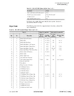
Page 495: ...pushbutton or the serial port SET P command to activate the LMD protocol Change the port PROTO setting from the default SEL to LMD to reveal the following settings PREFIX One character to precede the address This should be a character which does not occur in the course of other communications with the relay Valid choices are one of the following The default is ADDR Two character ASCII address The ...

Page 496: ... losing echoed characters while the external transmitter is warming up Step 4 Until the relay connection terminates you can use the standard commands that are available when PROTO is set to SEL Step 5 The QUIT command terminates the connection If no data are sent to the relay before the port timeup period it automatically terminates the connection Step 6 Enter the sequence Ctrl X QUIT CR before en...

Page 497: ...I data stream to continue This mechanism allows a single communications channel to be used for ASCII communications e g transmission of a long event report interleaved with short bursts of binary data to support fast acquisition of metering data The device connected to the other end of the link requires software that uses the separate data streams to exploit this feature The binary commands and AS...

Page 498: ...ast Meter Configuration Block A5D2 Demand Fast Meter Data Message A5C3 Peak Demand Fast Meter Configuration Block A5D3 Peak Demand Fast Meter Data Message A5CE Fast Operate Configuration Block A5E0 Fast Operate Remote Bit Control A5E3 Fast Operate Breaker Control A5ED Fast Operate Reset Command A546 Temperature Data Block Table D 2 ASCII Configuration Message List Request to Relay ASCII Response F...

Page 499: ...r configuration A5D1 Fast meter message A5C2 Fast demand configuration A5D2 Fast demand message A5C3 Fast peak configuration A5D3 Fast peak message 0002 Self test warning bit 5354410D0000 STA CR Check status 0003 Self test failure bit 5354410D0000 STA CR Check status 0004 Settings change bit A5C100000000 Reconfigure fast meter on settings change 0004 Settings change bit 53484F0D0000 SHO CR Check t...

Page 500: ...log channel data offset 0038 Time stamp offset 52 bytes 0040 Digital data offset 60 bytes 494157310000 IAW1 Analog channel name 00 Analog channel type integer 01 Scale factor type 4 byte float 00CA Scale factor offset Winding 1 494257310000 IBW1 00 01 00CA 494357310000 ICW1 00 01 00CA 494157320000 IAW2 00 01 00CE Winding 2 494257320000 IBW2 00 01 00CE 494357320000 ICW2 00 01 00CE 494157330000 IAW3...

Page 501: ... VDC 00 01 00DA xx Connection byte Based on PHROT and W1CT settings Calculation block 1 03 Current calculation only FFFF No skew adjustment FFFF No RS offset FFFF No XS offset 00 IAW1 01 IBW1 02 ICW1 FF NA FF NA FF NA xx Connection byte Based on PHROT and W2CT settings Calculation block 2 03 Current calculation only FFFF No skew adjustment FFFF No RS offset FFFF No XS offset 03 IAW2 04 IBW2 05 ICW...

Page 502: ... FFFF No XS offset 06 IAW3 07 IBW3 08 ICW3 FF NA FF NA FF NA xx Connection byte Based on PHROT and W4CT settings Calculation block 4 03 Current calculation only FFFF No skew adjustment FFFF No RS offset FFFF No XS offset 09 IAW4 0A IBW4 0B ICW4 FF NA FF NA FF NA xxxxxxxx Scale factor 200 Inom CTR1 Winding 1 xxxxxxxx Scale factor 200 Inom CTR2 Winding 2 xxxxxxxx Scale factor 200 Inom CTR3 Winding 3...

Page 503: ...essage length 128 bytes xx Status byte Bit 2 Usage Self test warning Bit 3 Usage Self test warning Bit 4 Usage Settings change 52 bytes Integers for the following IAW1 IBW1 ICW1 IAW2 IBW2 ICW2 IAW3 IBW3 ICW3 IAW4 IBW4 ICW4 VDC Imaginary values first followed by Real values 8 bytes Time stamp 63 bytes Digital banks targets 0 62 xx Checksum NOTE The Imaginary value for VDC is always zero Table D 6 A...

Page 504: ...000 334932573100 3I2W1 02 FF 0000 495257310000 IRW1 02 FF 0000 494157320000 IAW2 02 FF 0000 494257320000 IBW2 02 FF 0000 494357320000 ICW2 02 FF 0000 334932573200 3I2W2 02 FF 0000 495257320000 IRW2 02 FF 0000 494157330000 IAW3 02 FF 0000 494257330000 IBW3 02 FF Table D 6 A5C2 A5C3 Demand Peak Demand Fast Meter Configuration Messages Sheet 2 of 3 Data Description ...

Page 505: ...00 ICW3 02 FF 0000 334932573300 3I2W3 02 FF 0000 495257330000 IRW3 02 FF 0000 494157340000 IAW4 02 FF 0000 494257340000 IBW4 02 FF 0000 494357340000 ICW4 02 FF 0000 334932573400 3I2W4 02 FF 0000 495257340000 IRW4 02 FF 0000 00 Reserved xx Checksum Table D 6 A5C2 A5C3 Demand Peak Demand Fast Meter Configuration Messages Sheet 3 of 3 Data Description ...

Page 506: ...hannel listings in A5C2 00 Reserved xx Checksum Table D 8 A5CE Fast Operate Configuration Block Sheet 1 of 2 Data Description A5CE Command 42 Message length bytes 66 04 circuit breakers supported 0010 16 remote bits 01 Remote bit pulse supported 00 Reserved 31 Open breaker 1 11 Close breaker 1 32 Open breaker 2 12 Close breaker 2 33 Open breaker 3 13 Close breaker 3 34 Open breaker 4 14 Close brea...

Page 507: ...08 Clear remote bit RB9 28 Set remote bit RB9 48 Pulse remote bit RB9 09 Clear remote bit RB10 29 Set remote bit RB10 49 Pulse remote bit RB10 0A Clear remote bit RB11 2A Set remote bit RB11 4A Pulse remote bit RB11 0B Clear remote bit RB12 2B Set remote bit RB12 4B Pulse remote bit RB12 0C Clear remote bit RB13 2C Set remote bit RB13 4C Pulse remote bit RB13 0D Clear remote bit RB14 2D Set remote...

Page 508: ...Message length xx Operate code 0 F 20 2F 40 4F for remote bit clear set or pulse xx Operate validation 4 operate code 1 xx Checksum Table D 10 A5E3 Fast Operate Breaker Control Data Description A5E3 Command 06 Message length xx Operate code hex 31 34 open hex 11 14 close breakers 1 through 4 xx Operate validation 4 operate code 1 xx Checksum Table D 11 A5CD Fast Operate Reset Definition Block Data...

Page 509: ...tion 0xA546 Header code to flag the beginning of message 74h Message length 116 bytes 0000000000h Routing value 0 for point to point communication 00h Status byte 12h Function code unsolicited read response 00h Sequence byte 00h Pad byte xxxxxxxx Internal time since power up or rollover at 86400000 milliseconds xxxx External RTD Unit Status Bit 0 indicates the state of the external RTD power suppl...

Page 510: ...g starts with SER1 followed by SER2 SER3 and SER4 For example If SER1 50P11 OUT101 SER2 87U1 32IF SER3 OUT102 52A SER4 0 the name string will be 50P11 OUT101 87U1 32IF OUT102 52A If there are more than eight settings in SER the SNS message will have several rows Each row will have eight strings followed by the checksum and cartridge return The last row may have less than eight strings The ALIAS se...

Page 511: ...CII Commands Command Description CASCII Configuration message CBREAKER Breaker report CEVENT Event report Winding CEVENT DIF Event report Differential CHISTORY History report CSTATUS Status report CTARGET Target display CTHERMAL Thermal report CTHERMAL D 1 Transformer 1 daily thermal report CTHERMAL D 2 Transformer 2 daily thermal report CTHERMAL D 3 Transformer 3 daily thermal report CTHERMAL H 1...

Page 512: ... ASCII command as sent by the requesting device The naming convention for the Compressed ASCII commands is a C preceding the typical command For example CSTATUS abbreviated to CST is the compressed STATUS command l1 the minimum access level e g 1 or B or 2 at which the command is available H identifies a header line to precede one or more data lines is the number of subsequent ASCII names For exam...

Page 513: ... Compressed ASCII Commands CASCII Command General Format If a Compressed ASCII request is made for data that are not available e g the history buffer is empty or invalid event request the relay responds with the following message STX No Data Available 0668 CR ETX ...

Page 514: ...NUM MONTH DAY YEAR HOUR MIN SEC MSEC EVENT GROUP TARGETS yyyy CR 80D I I I I I I I I 7S I 52S yyyy CR CEV 1 yyyy CR 1H FID yyyy CR 1D 40S yyyy CR 7H MONTH_ DAY_ YEAR_ HOUR_ MIN_ SEC_ MSEC_ yyyy CR 1D I I I I I I I yyyy CR 5H FREQ SAM CYC_A SAM CYC_D NUM_OF_CYC EVENT yyyy CR 1D F I I F 7S yyyy CR 15H IAW1 IBW1 ICW1 IAW2 IBW2 ICW2 IAW3 IBW3 ICW3 IAW4 IBW4 ICW4 VDC TRIG NAMES OF ELEMENTS IN ALL RELAY...

Page 515: ...xxxx xxxx xxxx xxxx xxxx xxxx yyyy CR ETX CEVENT Command The CEV report contains every analog and digital element found in an EVE report and displays the information in Compressed ASCII format by sending CEV DIF R n Sx Ly w C Enter where yyyy the 4 byte ASCII representation of the hex checksum for the line H identifies a header line to precede one or more data lines is the number of subsequent ASC...

Page 516: ...nts on all windings and station battery averaged for 1 cycle Report Options Description n Event number Default to 1 Sx Samples per cycle x 4 or 8 See R option Default to 4 if Sx not specified Ly Display first y cycles of event report y 1 LER Default to L15 if Ly not specified Ly Displays event report from cycle y to end of report Ly w Displays event report from cycle y to cycle w C Default to 8 sa...

Page 517: ...g STX FID yyyy CR FID SEL 387 XXXX V0 ZXXXXXX DXXXXXXXX yyyy CR MONTH_ DAY_ YEAR_ HOUR_ MIN_ SEC_ MSEC_ yyyy CR xxxx xxxx xxxx xxxx xxxx xxxx xxxx yyyy CR REC_NUM MONTH DAY YEAR HOUR MIN SEC MSEC EVENT GROUP TARGETS yyyy CR xxxx xxxx xxxx xxxx xxxx xxxx xxxx xxxx xxxx xxxx xxxx yyyy CR continue previous line until all events are listed max 80 ETX CSTATUS Command Display the SEL 387 Compressed ASCI...

Page 518: ... yyyy CR ETX CTARGET Command Display the SEL 387 Compressed ASCII target display by sending CTA N Enter where N is one of the target numbers or element names accepted by the TAR command If N is omitted 0 is used The relay responds STX LLLL LLLL LLLL LLLL LLLL LLLL LLLL LLLL yyyy CR x x x x x x x x yyyy CR ETX where xxxx the data values corresponding to the first line labels yyyy the 4 byte ASCII r...

Page 519: ...R_ HOUR_ MIN_ SEC_ MSEC_ yyyy CR 1D I I I I I I I yyyy CR 19H BREAKER INT_TRIPS IAW IBW ICW EXT_TRIPS IAW IBW ICW POLE1 POLE2 POLE3 MONTH DAY YEAR HOUR MIN SEC MSEC yyyy CR 4D I I F F F I F F F I I I I I I I I I I yy yy CR CHI 1 yyyy CR 1H FID yyyy CR 1D 40S yyyy CR 7H MONTH_ DAY_ YEAR_ HOUR_ MIN_ SEC_ MSEC_ yyyy CR 1D I I I I I I I yyyy CR 11H REC_NUM MONTH DAY YEAR HOUR MIN SEC MSEC EVENT GROUP ...

Page 520: ...D I I I F F F F F F F F yyyy CR CTH D 3 1 yyyy CR 7H MONTH_ DAY_ YEAR_ HOUR_ MIN_ SEC_ MSEC_ yyyy CR 1D I I I I I I I yyyy CR 11H MONTH_ DAY_ YEAR_ Ambient Calc TopOil Msrd TopOil Hot Spot Load Max FAA RLOL TLOL yyyy CR 31D I I I F F F F F F F F yyyy CR CTH H 1 1 yyyy CR 7H MONTH_ DAY_ YEAR_ HOUR_ MIN_ SEC_ MSEC_ yyyy CR 1D I I I I I I I yyyy CR 12H MONTH_ DAY_ YEAR_ HOUR_ MIN_ CommError Ambient C...

Page 521: ...xxxx xxxx xxxx yyyy CR xxxx xxxx xxxx xxxx xxxx xxxx xxxx xxxx xxxx xxxx xxxx xxxx xxxx xxxx xxxx xxxx xxxx xxxx xxxx yyyy CR xxxx xxxx xxxx xxxx xxxx xxxx xxxx xxxx xxxx xxxx xxxx xxxx xxxx xxxx xxxx xxxx xxxx xxxx xxxx yyyy CR ETX CEVENT Command The CEV report contains every analog and digital element found in an EVE report and displays the information in Compressed ASCII format by sending CEV D...

Page 522: ...ts on all windings and station battery averaged for 1 cycle Report Options Description n Event number Default to 1 Sx Samples per cycle x 4 or 8 See R option Default to 4 if Sx not specified Ly Display first y cycles of event report y 1 LER Default to L15 if Ly not specified Ly Displays event report from cycle y to end of report Ly w Displays event report from cycle y to cycle w C Default to 8 sam...

Page 523: ...y CR FID SEL 387 XXXX V0 ZXXXXXX DXXXXXXXX yyyy CR MONTH_ DAY_ YEAR_ HOUR_ MIN_ SEC_ MSEC_ yyyy CR xxxx xxxx xxxx xxxx xxxx xxxx xxxx yyyy CR REC_NUM MONTH DAY YEAR HOUR MIN SEC MSEC EVENT GROUP TARGETS yyyy CR xxxx xxxx xxxx xxxx xxxx xxxx xxxx xxxx xxxx xxxx xxxx yyyy CR continue previous line until all events are listed max 80 ETX CSTATUS Command Display the SEL 387 Compressed ASCII status repo...

Page 524: ...rmal Report Command Display the following thermal reports in Compressed ASCII format by sending CTH H D T phase Enter CTH Event Report If no parameters are specified on the command line all archived thermal event reports are displayed To obtain thermal event reports send the following where xxxx the data values corresponding to the first line labels yyyy the 4 byte ASCII representation of the hex ...

Page 525: ...l Hot Spot Load Max FAA RLOL TLOL yyyy CR xxxx xxxx xxxx xxxx xxxx xxxx xxxx xxxx xxxx xxxx xxxx yyyy CR previous line repeated until all archive data is listed ETX To obtain the report for Phase B send the following CTH D 2 Enter STX MONTH_ DAY_ YEAR_ HOUR_ MIN_ SEC_ MSEC_ yyyy CR xxxx xxxx xxxx xxxx xxxx xxxx xxxx yyyy CR MONTH_ DAY_ YEAR_ Ambient Calc TopOil Msrd TopOil Hot Spot Load Max FAA RL...

Page 526: ...y CR xxxx xxxx xxxx xxxx xxxx x xxxx xxxx xxxx xxxx xxxx xxxx xxxx yyyy CR previous line repeated until all archive data is listed ETX To obtain the report for Phase C send the following CTH H 3 Enter STX MONTH_ DAY_ YEAR_ HOUR_ MIN_ SEC_ MSEC_ yyyy CR xxxx xxxx xxxx xxxx xxxx xxxx xxxx yyyy CR MONTH_ DAY_ YEAR_ HOUR_ MIN_ ComError Ambient Calc TopOil Msrd TopOil Hot Spot Load FAA yyyy CR xxxx xxx...

Page 527: ... 0 5 6 Relay Compressed ASCII Commands SEL 387 6 Relay If no data are available the relay replies No Data Available 0668 CR where xxxx data values corresponding to the first line labels yyyy the 4 byte ASCII representation of the checksum for the line ...

Page 528: ...This page intentionally left blank ...
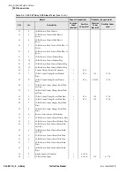
Page 529: ...gle communications channel for ASCII communications e g transmission of a long event report interleaved with short bursts of binary data to support fast acquisition of metering or SER data To exploit this feature the device at the other end of the link requires software that uses the separate data streams A device that does not interleave the data streams can also access the binary commands and AS...

Page 530: ...SER messages Step 2 When SER records are triggered in theSEL 387 the relay responds with an unsolicited binary SER message If this message has a valid checksum it must be acknowledged by sending an acknowledge message with the same response number as that contained in the original message The relay will wait about 100 ms to 500 ms to receive an acknowledge message at which time the relay will rese...

Page 531: ...ansmits it If there are more than nn new records available or if the first and last records are separated by more than 16 seconds the relay will break the transmission into multiple messages so that no message contains more than nn records and the first and last records of each message are separated by no more than 16 seconds If the function to enable is not 18 or the function code is not recogniz...

Page 532: ...lso passed as data in the Enable Unsolicited Data Transfer and the Disable Unsolicited Data Transfer messages to indicate which type of unsolicited data should be enabled or disabled The message format for function code 0x18 is shown below Data Description A546 Message header 10 Message length 16 decimal 0000000000 Five bytes reserved for future use as a routing address YY Status byte LSB 1 indica...

Page 533: ...he time of day field xx last element index uuuuuu Three byte time tag offset of last element in microseconds since time indicated in the time of day field FFFFFFFE Four byte end of records flag ssssssss Packed four byte element status for up to 32 elements LSB for the 1st element cccc Two byte CRC 16 checkcode for message Data Description A546 Message header 22 Message length 34 decimal 0000000000...

Page 534: ...owledge requested A5 46 10 00 00 00 00 00 01 02 C0 XX 18 00 cc cc XX 0 1 2 3 EXAMPLE F 4 Successful acknowledge from the relay for the Disable Unsolicited Data Transfer message A5 46 0E 00 00 00 00 00 00 82 00 XX cc cc XX is the same as the response number in the Disable Unsolicited Data Transfer message to which it responds EXAMPLE F 5 Successful acknowledge message from the master for an unsolic...

Page 535: ...mber If the relay does not receive an acknowledge from the master before approximately 500 ms the relay will resend the same message packet with the same response number until it receives an acknowledge message with that response number For the next SER message the relay will increment the response number it will wrap around to zero from three A single SER message packet from the relay can have a ...

Page 536: ...This page intentionally left blank ...

Page 537: ...relays support Distributed Network Protocol DNP3 Level 2 Slave protocol This includes access to metering data protection elements Relay Word contact I O targets Sequential Events Recorder breaker monitor relay summary event reports settings groups and time synchronization The SEL 387 Relay supports DNP point remapping and virtual terminal object ...

Page 538: ...30 minutes 5 DNPADR DNP Address 0 65534 0 MODEM Modem connected to port Y N N MSTR Modem startup string up to 30 characters E0X0 D0S0 2 PH_NUM Phone number to dial out to up to 30 characters MDTIME Time to attempt dial 5 300 seconds 60 MDRETI Time between dial out attempts 5 3600 seconds 120 MDRETN Number of dial out attempts 0 5 3 ECLASSA Class for Analog event data 0 for no event 1 3 2 ECLASSB C...

Page 539: ...S If the PSTDLY time delay is in progress RTS still high following a transmission and another transmission is initiated the SEL 387 transmits the message without completing the PSTDLY delay and without any preceding PREDLY delay The RTS CTS handshaking can be completely disabled by setting PREDLY to OFF In this case RTS is forced high and CTS is ignored with only received characters acting as a DC...

Page 540: ... a message will be corrupted Thus the number of retries should be set higher on noisy channels Set the data link time out long enough to allow for the worst case response of the master plus transmission time When the SEL 387 decides to transmit on the DNP link it has to wait if the physical connection is in use The SEL 387 monitors physical connections by using CTS input treated as a Data Carrier ...

Page 541: ...tic The master polls for static Class 0 data only Set CLASS 0 Set UNSOL N Polled Report by Exception The master polls frequently for event data and occasionally for static data Set CLASS to a non zero value Set UNSOL N Unsolicited Report by Exception The slave devices send unsolicited event data to the master and the master occasionally sends integrity polls for static data Set CLASS to a non zero...

Page 542: ...tion Configurable by setting Maximum application fragment size transmitted received octets 2048 Maximum application layer retries None Requires application layer confirmation When reporting Event Data Data link confirm time out Configurable Complete application fragment time out None Application confirm time out Configurable Complete Application response time out None Executes control WRITE binary...

Page 543: ... 7 8 129 0 1 7 8 1 2a Binary Input With Status 1 0 1 6 7 8 129 0 1 7 8 2 0 Binary Input Change All Variations 1 6 7 8 2 1 Binary Input Change Without Time 1 6 7 8 129 17 28 2 2a Binary Input Change With Time 1 6 7 8 129 130 17 28 2 3 Binary Input Change With Relative Time 1 6 7 8 129 17 28 10 0 Binary Output All Variations 1 0 1 6 7 8 10 1 Binary Output 10 2a Binary Output Status 1 0 1 6 7 8 129 0...

Page 544: ...nter Change Event With out Time 22 5 32 Bit Counter Change Event With Time 1 6 7 8 129 17 28 22 6 16 Bit Counter Change Event With Time 1 6 7 8 129 17 28 22 7 32 Bit Delta Counter Change Event With Time 22 8 16 Bit Delta Counter Change Event With Time 23 0 Frozen Counter Event All Variations 23 1 32 Bit Frozen Counter Event Without Time 23 2 16 Bit Frozen Counter Event Without Time 23 3 32 Bit Fro...

Page 545: ...ariations 33 1 32 Bit Frozen Analog Event Without Time 33 2 16 Bit Frozen Analog Event Without Time 33 3 32 Bit Frozen Analog Event With Time 33 4 16 Bit Frozen Analog Event With Time 40 0 Analog Output Status All Variations 1 0 1 6 7 8 40 1 32 Bit Analog Output Status 1 0 1 6 7 8 129 0 1 7 8 40 2a 16 Bit Analog Output Status 1 0 1 6 7 8 129 0 1 7 8 41 0 Analog Output Block All Variations 41 1 32 ...

Page 546: ...Decimal 112 All Virtual Terminal Output Block 2 6 113 All Virtual Terminal Event Data 1 20 21 6 129 130 17 28 No object 13 14 23 a Default Table G 4 SEL 387 Relay DNP Object Table Sheet 4 of 4 Object Request supported Response may generate Obj Var Description Function Codes decimal Qualifier Codes hex Function Codes decimal Qualifier Codes hex Table G 5 SEL 387 Relay Wye Delta DNP Data Map Sheet 1...

Page 547: ...41 Read next relay event 20 22 00 Active settings group 20 22 01 Internal breaker trips1 20 22 02 Internal breaker trips 2 20 22 03 Internal breaker trips 3 20 22 04 Internal breaker trips 4 20 22 05 External breaker trips 1 20 22 06 External breaker trips 2 20 22 07 External breaker trips 3 20 22 08 External breaker trips 4 30 32 00 01 IA magnitude and angle for Wdg 1 30 32 02 03 IB magnitude and...

Page 548: ...rent 30 32 53 IRT3 Restraint Current 30 32 54 I1F2 Second Harmonic Current 30 32 55 I2F2 Second Harmonic Current 30 32 56 I3F2 Second Harmonic Current 30 32 57 I1F5 Fifth Harmonic Current 30 32 58 I2F5 Fifth Harmonic Current 30 32 59 I3F5 Fifth Harmonic Current 30 32 60 VDC 30 32 61 65 Demand A B C 3I2 and IR magnitudes for Wdg 1 30 32 66 70 Demand A B C 312 and IR magnitudes for Wdg 2 30 32 71 75...

Page 549: ...IC time in DNP format for Wdg 3 30 32 133 Peak demand 312 mag for Wdg 3 30 134 136 Peak demand 312 time in DNP format for Wdg 3 30 32 137 Peak demand IR mag for Wdg 3 30 138 140 Peak demand IR time in DNP format for Wdg 3 30 32 141 Peak demand IA mag for Wdg 4 30 142 144 Peak demand IA time in DNP format for Wdg 4 30 32 145 Peak demand IB mag for Wdg 4 30 146 148 Peak demand IB time in DNP format ...

Page 550: ...and SEL 387 6 Relays Continuation of Wye Delta DNP Data Map SEL 387 5 Relay SEL 387 6 Relay Type Index Description Type Index Description 30 32 173 200 Reserved 30 32 173 Ambient temperature 30 32 201 Event type See Event Cause table following 30 32 174 176 Thermal Load A B C 30 32 202 Fault Targets bit 15 EN bit 8 51 and bit 7 A bit 0 W4 30 32 177 179 In Service Cooling System A B C 30 32 203 214...

Page 551: ... setting Analog inputs are scanned at approximately a second rate except for analogs 201 218 During a scan all events generated will use the time the scan was initiated Analogs 201 218 are derived from the history queue data for the most recently read fault and do not generate event messages Analog 201 is defined as follows If Analog 201 is 0 fault information has not been read and the related ana...

Page 552: ...h On 3 Latch Off 4 Pulse On 1 Pulse Off 2 0 15 Set Clear Set Clear Pulse Clear 16 23 Pulse Do nothing Pulse Do nothing Pulse Do nothing 24 Pulse RB2 Pulse RB1 Pulse RB2 Pulse RB1 Pulse RB2 Pulse RB1 25 Pulse RB4 Pulse RB3 Pulse RB4 Pulse RB3 Pulse RB4 Pulse RB3 26 Pulse RB6 Pulse RB5 Pulse RB6 Pulse RB5 Pulse RB6 Pulse RB5 27 Pulse RB8 Pulse RB7 Pulse RB8 Pulse RB7 Pulse RB8 Pulse RB7 28 Pulse RB1...

Page 553: ... 208 29 IN216 IN215 IN214 IN213 IN212 IN211 IN210 IN209 223 216 30 IN308 IN307 IN306 IN305 IN304 IN303 IN302 IN301 231 224 31 IN316 IN315 IN314 IN313 IN312 IN311 IN310 IN309 239 232 32 S1V1 S1V2 S1V3 S1V4 S1V1T S1V2T S1V3T S1V4T 247 240 33 S2V1 S2V2 S2V3 S2V4 S2V1T S2V2T S2V3T S2V4T 255 248 34 S3V1 S3V2 S3V3 S3V4 S3V5 S3V6 S3V7 S3V8 263 256 35 S3V1T S3V2T S3V3T S3V4T S3V5T S3V6T S3V7T S3V8T 271 26...

Page 554: ...vent is loaded If no further event summaries are available attempting to load the next event will cause the event type analog point 201 to be set to 0 50 c c c c c c c c 391 384 53 49A01A 49T01A 49A02A 49T02A 49A03A 49T03A 49A04A 49T04A 415 408 54 49A05A 49T05A 49A06A 49T06A 49A07A 49T07A 49A08A 49T08A 423 416 55 49A09A 49T09A 49A10A 49T10A 49A11A 49T11A 49A12A 49T12A 431 424 56 49A01B 49T01B 49A0...

Page 555: ... command is issued without parameters the relay displays all of the maps with the following format DNP Enter Binary Inputs Default Map Binary Outputs Default Map Counters Default Map Analog Inputs 112 28 17 35 1 56 57 58 59 60 61 62 63 64 65 66 67 100 101 102 103 Analog Outputs Off If the DNP command is issued with an object type specified AI AO BI BO C and the VIEW parameter the relay displays on...

Page 556: ...anges not saved Custom Scaling In addition to remapping these commands can be used on analog inputs to create custom scaling and dead bands per point Scaling is done by adding a semicolon and scaling factor to a point reference The base value will be multiplied by the scaling factor before reporting it This is done instead of the DECPLA setting that would normally apply Dead bands are added using ...

Page 557: ...caller connects to the modem in the SEL 387 the SEL 387 will disconnect the modem if there have been no transactions for the TIMEOUT time Virtual Terminal The purpose of this Virtual Terminal VT Protocol is to allow ASCII data transfers between a master and an SEL relay over a DNP port DNP3 objects 112 and 113 are used for embedding the ASCII communications over the DNP port At the master each sla...

Page 558: ...icit connections exist by the mere presence of a VT compatible Slave IED Virtual terminal supports all ASCII commands listed in the SEL 387 Relay Command Summary You do not need a password to login to a virtual terminal session through a DNP port but you will need the appropriate access levels for setting changes and breaker operations A virtual terminal session times out in the same way as an ASC...

Page 559: ...y event data 0 for no event 1 3 ECLASSB Class for Counter event data 0 for no event 1 3 ECLASSC Currents scaling 0 3 decimal places DECPLA Time set request interval minutes 0 for never 1 32767 TIMERQ Select Operate time out interval seconds 0 0 30 0 STIMEO Data link time out interval seconds 0 5 DTIMEO Minimum Delay from DCD to transmission seconds 0 00 1 00 MINDLY Maximum Delay from DCD to transm...

Page 560: ...lay DNP Port SET P Settings Sheet SEL 387 0 5 6 Relay Instruction Manual Date Code 20050919 Date________________ Number of events to transmit on 1 200 NUMEVE Age of oldest event to force transmit on seconds 0 0 60 0 AGEEVE ...

Page 561: ...resently in the relay DAT m d y Enter date in this manner if Date Format setting DATE_F MDY DAT y m d Enter date in this manner if Date Format setting DATE_F YMD EVE n Show standard event report number n with 1 4 cycle resolution Attach S8 for 1 8 cycle resolution EVE D n Show digital data event report number n with 1 4 cycle resolution Attach S8 for 1 8 cycle resolution EVE DIF1 n Show differenti...

Page 562: ...gs STA Show relay self test status STA C Clear relay status report from memory and reboot the relay TAR n k Show Relay Word row n status n 0 through 41 Enter number k to scroll Relay Word row n status k times on screen Append F to display targets on the front panel second row of LEDs TAR R Return front panel LED targets to regular operation and reset the tripping front panel targets All commands t...

Page 563: ...winding event report number n at 1 4 cycle resolution Attach DIF for compressed differential element report at 1 4 cycle resolution Attach R for compressed raw winding data report at 1 16 cycle resolution Attach Sm for 1 m cycle resolution m 4 or 8 for filtered data m 4 8 16 32 or 64 for raw data CLO n Assert the CCn Relay Word bit Used to close breaker n if CCn is assigned to an output contact JM...

Page 564: ...s SER d1 Show rows in the Sequential Events Recorder SER event report for date d1 SER d1 d2 Show rows in the Sequential Events Recorder SER event report from date d1 to d2 Entry of dates is dependent on the Date Format setting DATE_F MDY or YMD SER m n Show rows m through n in the Sequential Events Recorder SER event report SER n Show the latest n rows in the Sequential Events Recorder SER event r...

Page 565: ...ce the relay prompts for the entry of the Access Level 1 password in order to enter Access Level 1 BAC Enter Access Level B If the main board password jumper JMP6A is not in place the relay prompts for the entry of the Access Level B password in order to enter Access Level B BRE Breaker report shows trip counters trip currents and wear data for up to four breakers BRE R n Reset trip counters trip ...

Page 566: ...eenth harmonic levels in secondary amperes MET DIF k Display differential metering data in multiples of TAP Enter number k to scroll metering k times on screen MET P k Display peak demand metering data in primary amperes Enter number k to scroll metering k times on screen MET RD n Reset demand metering values n 1 2 3 4 A MET RP n Reset peak demand metering values n 1 2 3 4 A MET SEC k Display mete...

Page 567: ...gh fault event data The twenty 20 most recent individual events are displayed TFE n Displays cumulative and individual through fault event data The n most recent individual events are displayed where n 1 to 1200 TFE A Displays cumulative and individual through fault event data All the most recent individual events are displayed up to 1200 TFE C Clears resets cumulative and individual through fault...

Page 568: ...he relay by entering just TIM Example time 22 47 36 is entered with command TIM 22 47 36 TRI Trigger an event report Access Level 2 Commands The Access Level 2 commands primarily allow the user to change settings or operate relay parameters and output contacts All Access Level 1 commands can also be executed from Access Level 2 The screen prompt is ...

Reviews: