3.3
Date Code 20050919
Instruction Manual
SEL-387-0, -5, -6 Relay
Differential, Restricted Earth Fault, Thermal, and Overcurrent Elements
Differential Element
Four digital band-pass filters extract the fundamental, second, fourth (all but
SEL-387-0), and fifth (not shown) harmonics of the input currents. A dc filter
(not shown) forms one cycle sums of the positive and negative values.
Using the transformer MVA rating as a common reference point, TAP scaling
converts all secondary currents entering the relay from the four windings to
per-unit values, thus changing the ampere values into dimensionless multiples
of TAP. Throughout the text, the term “TAP” refers to the per-unit value
common to all four windings, whereas “TAP
n
” refers to the ampere value of a
particular winding(s); TAPmin and TAPmax refer to the least and greatest of
the four TAP
n
values. This method ensures that, for full-load through-current
conditions, all incoming current multiples of TAP sum to 1.0 and all outgoing
current multiples of TAP sum to –1.0, with a reference direction into the
transformer windings.
Transformer and CT connection compensation adjusts the sets of three-phase
currents for the phase angle and phase interaction effects introduced by the
winding connection of the transformer and CTs. Settings W1CTC through
W4CTC determine the mathematical corrections to the three-phase currents
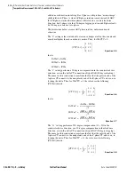
for Winding 1 through Winding 4, respectively. CTC1 is shown in
as the phase angle and sequence quantity adjustment for Winding 1.
I1W1C1, I2W1C1, and I3W1C1 are the fundamental frequency A-phase,
B-phase, and C-phase compensated currents for Winding 1. Similarly,
I1W1C2, I2W1C2, and I3W1C2 are the second-harmonic compensated
currents for Winding 1. The dc, fourth-harmonic, and fifth-harmonic
compensated currents use similar names. The I1 compensated currents are
used with differential element 87-1, I2 with element 87-2, and I3 with element
87-3.
Figure 3.2
Winding 1 Compensated Currents
illustrate how the IOP1 (operate), IRT1 (restraint),
IHRT1 (harmonic restraint, all but SEL-387-0 Relay), I1HB2 (second
harmonic), and I1HB4 (fourth harmonic, all but SEL-387-0) quantities are
calculated for the 87-1 element. IOP1 is generated by summing the winding
currents in a phasor addition. IRT1 is generated by summing the magnitudes
of the winding currents in a simple scalar addition and dividing by two. The
87-2 and 87-3 quantities are calculated in a similar manner.
For each restraint element (87R-1, 87R-2, 87R-3), the quantities are summed
as phasors and the magnitude becomes the Operate quantity (IOP
n
). For a
through-current condition, IOPn should calculate to about 1 + (–1) = 0, at
rated load. Calculation of the Restraint quantity (IRT
n
) occurs through a
summation of all current magnitudes and then division by two. For a through-
current condition, this will calculate to about (| 1 | + | –1 |) / 2 = 2 / 2 = 1, at
rated load.
Data
Acquisition
Fundamental
Frequency
Filter
TAP1
Scaling
Connection
Compensation
(CTC1)
Second-
Harmonic
Filter
TAP1
Scaling
Connection
Compensation
(CTC1)
Fourth-
Harmonic
Filter
TAP1
Scaling
Connection
Compensation
(CTC1)
I1W1C2
I2W1C2
I3W1C2
I1W1C4
I2W1C4
I3W1C4
I1W1C1
I2W1C1
I3W1C1
IAW1
IBW1
ICW1
Summary of Contents for SEL-387-0
Page 10: ...This page intentionally left blank ...
Page 16: ...This page intentionally left blank ...
Page 56: ...This page intentionally left blank ...
Page 350: ...This page intentionally left blank ...
Page 388: ...This page intentionally left blank ...
Page 456: ...This page intentionally left blank ...
Page 494: ...This page intentionally left blank ...
Page 528: ...This page intentionally left blank ...


