3.28
SEL-387-0, -5, -6 Relay
Instruction Manual
Date Code 20050919
Differential, Restricted Earth Fault, Thermal, and Overcurrent Elements
Temperature Measurement (SEL-387-5 and SEL-387-6 Relays)
Example of Setting the SEL-387 for a Three-Winding Transformer
In this section we use an example that forms the basis of the default
differential settings we entered at the factory before shipping the relay. The
example represents a typical three-winding transformer application and
demonstrates the use of CT compensation settings and tap calculations.
illustrates the application. The transformer is a 230 kV to 138 kV
autotransformer with a 13.8 kV delta tertiary whose terminals we have
brought out and included in the differential zone of protection. The
transformer primary and secondary have a maximum rating of 100 MVA,
while the tertiary has a rating of 30 MVA. All three windings have wye-
connected current transformers, with ratios of 600/5 A at 230 kV, 1200/5 A at
138 kV, and 2000/5 A at 13.8 kV. We have connected the transformer per
IEEE standards, with the low voltage delta lagging the high-voltage wye by
30 degrees.
Step 1. Set the appropriate enables.
Because we need only three terminals for the differential zone,
make the first settings as follows:
E87W1 =
Y
E87W2 =
Y
E87W3 =
Y
These settings enable Windings 1, 2, and 3, leaving Winding 4 available for
stand-alone overcurrent duty.
Step 2. Select settings for the current transformer connection and ratio
for each winding.
All CTs connect in wye. The ratios are equal to primary current
divided by secondary current. The settings are as follows:
Step 3. Set the transformer maximum rating. We use this rating for all
windings in the later tap calculation:
MVA =
100
Step 4. Decide whether to use internal CT compensation and determine
compensation settings.
Because there are both wye and delta transformer windings but
only wye CTs, we must adjust for the phase angle shift. In the
“traditional” differential relay connection the wye transformer
windings would have their CTs connected in delta to produce a
shift in the same direction as that produced in the transformer.
In this case a “DAC” or “30-degree lagging” connection would
have been used. This would not only shift the currents, but it
would remove the zero-sequence current component by
physically subtracting the appropriate phase currents via the
delta connection. We achieve the same effect within the relay
by using the selected compensation. The settings are:
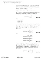
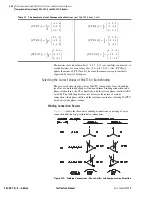
ICOM =
Y
(choose to define the CT compensation)
W1CTC =
11
230 kV
138 kV
13.8 kV
W1CT = Y
W2CT = Y
W3CT = Y
CTR1 = 120
CTR2 = 240
CTR3 = 400
Summary of Contents for SEL-387-0
Page 10: ...This page intentionally left blank ...
Page 16: ...This page intentionally left blank ...
Page 56: ...This page intentionally left blank ...
Page 350: ...This page intentionally left blank ...
Page 388: ...This page intentionally left blank ...
Page 456: ...This page intentionally left blank ...
Page 494: ...This page intentionally left blank ...
Page 528: ...This page intentionally left blank ...


