10.13
Date Code 20050919
Instruction Manual
SEL-387-0, -5, -6 Relay
Testing and Troubleshooting
Acceptance Testing
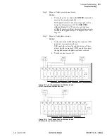
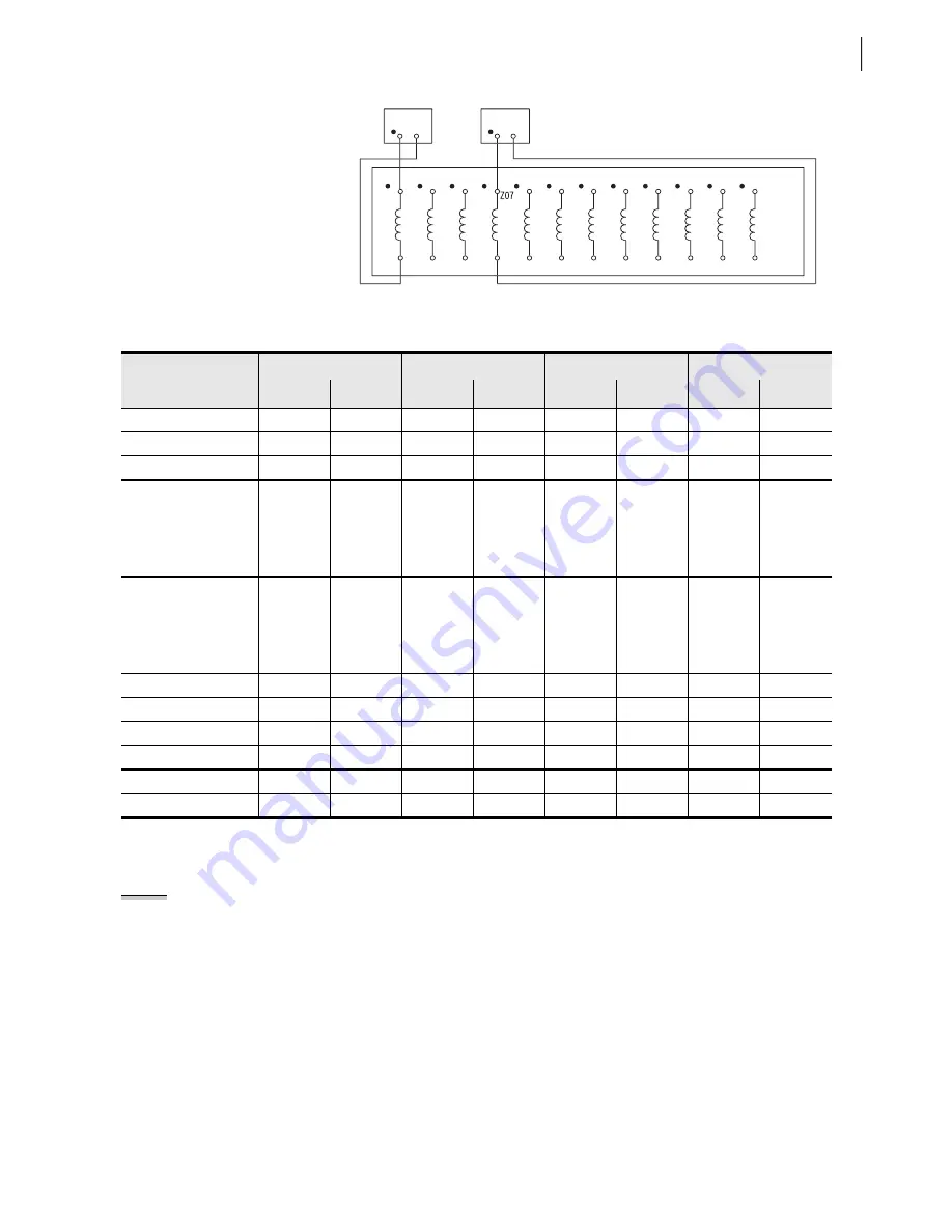
Figure 10.5
Test Connections for Two Single Current Test Sources
Definite-Time and Inverse-Time Overcurrent Elements
Step 1. Purpose: Determine the expected time delay for the overcurrent
element.
Method:
a. Execute the
SHO
command via the relay front panel or
serial port and verify the time delay settings (i.e.,
SHO
51P1 <Enter>
). The delay settings will follow the
pickup settings when they are displayed.
b. Calculate the time delay to pickup (tp).
Definite-time elements will be equal to the delay setting
(i.e., 50P11D setting for the 50P11 element). Inverse-
time elements are calculated using three element
settings and the operating time equations shown in
Section 3: Differential, Restricted Earth Fault,
Z01
Z02
IAW1
Z04
Z03
IBW1
Z06
Z05
ICW1
Z08
IAW2
Z10
Z09
IBW2
Z12
Z11
ICW2
Z14
Z13
IAW3
Z16
Z15
IBW3
Z18
Z17
ICW3
Z20
Z19
IAW4
Z22
Z21
IBW4
Z24
Z23
ICW4
SEL-387
(partial)
Current
Source 1
Current
Source 2
Table 10.2
Instantaneous Overcurrent Elements and Corresponding Settings
Winding 1
Winding 2
Winding 3
Winding 4
Bit
Setting
Bit
Setting
Bit
Setting
Bit
Setting
Phase
Level
1
50P11 50P11P
50P21 50P21P
50P31 50P31P
50P41 50P41P
Phase
Level
2
50P12 50P12P
50P22 50P22P
50P32 50P32P
50P42 50P42P
Phase
Inverse-Time
51P1 51P1P
51P2 51P2P
51P3 51P3P
51P4 51P4P
A-Phase
Level
3
50A13 50P13P
50A23 50P23P
50A33 50P33P
50A43 50P43P
B-Phase Level 3
50B13
50B23
50B33
50B43
C-Phase Level 3
50C13
50C23
50C33
50C43
Phase Level 3
50P13
50P23
50P33
50P43
A-Phase Level 4
50A14
50P14P
50A24
50P24P
50A34
50P34P
50A44
50P44P
B-Phase Level 4
50B14
50B24
50B34
50B44
C-Phase Level 4
50C14
50C24
50C34
50C44
Phase Level 4
50P14
50P24
50P34
50P44
Residual
Level
1
50N11 50N11P
50N21 50N21P
50N31 50N31P
50N41 50N41P
Residual
Level
2
50N12 50N12P
50N22 50N22P
50N32 50N32P
50N42 50N42P
Residual
Inverse-Time
51N1 51N1P
51N2 51N2P
51N3 51N3P
51N4 51N4P
Neg-Seq
Level
1
50Q11 50Q11P
50Q21 50Q21P
50Q31 50Q31P
50Q41 50Q41P
Neg-Seq
Level
2
50Q12 50Q12P
50Q22 50Q22P
50Q32 50Q32P
50Q42 50Q42P
Neg-Seq
Inverse-Time
51Q1 51Q1P
51Q2 51Q2P
51Q3 51Q3P
51Q4 51Q4P
NOTE:
This example tests the
Winding 1 51P1 phase inverse-time
overcurrent element. Use the same
procedure to test all definite-time and
inverse-time overcurrent elements for
each winding.
Summary of Contents for SEL-387-0
Page 10: ...This page intentionally left blank ...
Page 16: ...This page intentionally left blank ...
Page 56: ...This page intentionally left blank ...
Page 350: ...This page intentionally left blank ...
Page 388: ...This page intentionally left blank ...
Page 456: ...This page intentionally left blank ...
Page 494: ...This page intentionally left blank ...
Page 528: ...This page intentionally left blank ...


