4.32
SEL-787 Relay
Instruction Manual
Date Code 20081022
Protection and Logic Functions
Basic Protection
NOTE:
The cosine filter provides
excellent performance in removing dc
offset and harmonics. However, the
bipolar peak detector has the best
performance in situations of severe
CT saturation when the cosine filter
magnitude estimation is significantly
degraded. Combining the two
methods provides an elegant solution
for ensuring dependable short circuit
overcurrent element operation.
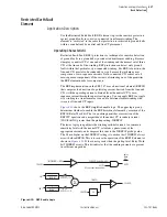
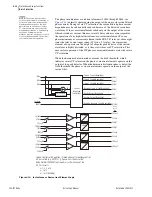
The phase instantaneous overcurrent elements (50P
n
1 through 50P
n
4; see
) normally operate using the output of the one cycle cosine filtered
phase current. During severe CT saturation, the cosine filtered phase current
magnitude may be substantially reduced because of the distorted secondary
waveform. If the overcurrent element relied only on the output of the cosine
filtered secondary current, this may severely delay and may even jeopardize
the operation of any high-set instantaneous overcurrent element. For any
phase instantaneous overcurrent element in the SEL-787 relay set above eight
times the relay current input rating (40 A in a 5 A relay), the overcurrent
element also operates on the output of a bipolar peak detector if the current
waveform is highly distorted, as is the case with severe CT saturation. This
ensures fast operation of the 50P phase overcurrent elements even with severe
CT saturation.
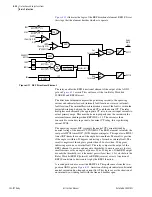
When the harmonic distortion index exceeds the fixed threshold, which
indicates severe CT saturation, the phase overcurrent elements operate on the
output of the peak detector. When the harmonic distortion index is below the
fixed threshold, the phase overcurrent elements operate on the output of the
cosine filter.
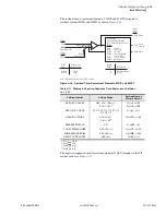
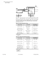
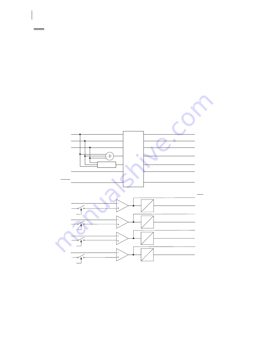
Figure 4.14
Instantaneous Overcurrent Element Logic
IAWn
IBWn
ICWn
IN1
PHROT
IGWn
Current
Magnitude
Calculations
|IPWn|
|IN1|
|IGWn|
50PnxP
50PnxT
50N1yP
50N1yT
Settings
(Maximum Phase Current Magnitude)
(Neutral Current Magnitude)
(Residual Current Magnitude)
50N1yD
0
50PnxD
0
Negative-Sequence
Current Calculation
(Negative-Sequence Current Magnitude)
|3I2Wn|
50GnyP
50GnyT
50QnyP
50QnyT
50QnyD
0
50GnyD
0
|IAWn|
|IBWn|
(Phase A Current Magnitude)
(Phase B Current Magnitude)
(Phase C Current Magnitude)
|ICWn|
50QnyP
50GnyP
50N1yP
|312Wn|
50QnyTC
|IGWn|
50GnyTC
|IN1|
50N1yTC
|IPWn|
50PnxTC
Torque Control switch position = Closed when corresponding control
bit is asserted (e.g., 50P11TC = 1), Open when it is deasserted.
Relay Word bit ORED50T (not shown) asserts when any of the
50_T bit asserts.
x = 1, 2, 3, or 4
y = 1 or 2
n = 1 or 2 (Winding)
50PnxP
Relay
Word
Bits
Summary of Contents for SEL-787
Page 1: ...20081022 SEL 787 Transformer Protection Relay Instruction Manual PM787 01 NB ...
Page 6: ...This page intentionally left blank ...
Page 12: ...This page intentionally left blank ...
Page 18: ...This page intentionally left blank ...
Page 78: ...This page intentionally left blank ...
Page 206: ...This page intentionally left blank ...
Page 280: ...This page intentionally left blank ...
Page 334: ...This page intentionally left blank ...
Page 376: ...This page intentionally left blank ...
Page 388: ...This page intentionally left blank ...
Page 474: ...This page intentionally left blank ...
Page 508: ...This page intentionally left blank ...

