4.55
Date Code 20081022
Instruction Manual
SEL-787 Relay
Protection and Logic Functions
Voltage-Based Protection
Collect this information before calculating volts/hertz element settings:
➤
Transformer manufacturer's overexcitation limit curve
➤
Transformer nominal phase-phase voltage
Select the transformer winding that is most likely to suffer overexcitation. The
relay voltage input should be from a source that most reliably reflects that
winding voltage.
Set E24 := Y to enable volts/hertz protection elements. If you do not need
volts/hertz protection, set E24 := N. When E24 := N, the 24TC, 24D1, 24D1T,
24C2, 24C2T, and 24CR Relay Word bits are inactive. The relay hides
corresponding settings; you do not need to enter these settings.
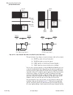
When three PTs are available, the most common PT winding connection is to
connect both HV and LV sides in wye, leaving the power transformer winding
connections as the only variable. For wye-connected power transformer
windings, the power transformer phase-to-neutral voltage is readily measured
through wye-wye connected PTs. Set 24WDG := WYE. When the power
transformer windings are delta connected, the relay cannot measure the phase
voltage directly, but needs to calculate the voltage values. The relay calculates
the differences between the voltages presented to the relay from the wye-wye
connected PTs and thus the voltage connected to the power transformer
windings. Set 24WDG := DELTA. Thus, voltage values selection to calculate
the volts/hertz protection and sequence components is based on the 24WDG
selection; phase to phase for 24WDG := DELTA and phase-to-neutral for
24WDG = WYE.
Use the Level 1 volts/hertz element as an overexcitation alarm. Set 24D1P
equal to or greater than 105 percent, but less than the minimum pickup of the
Level 2 element. Use a 24D1D time delay of 1.0 second to allow time for
correction of an overexcitation condition prior to an alarm.
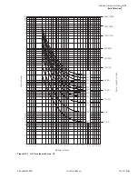
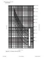
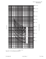
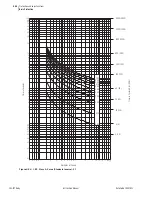
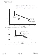
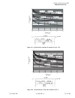
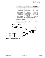
The 24CCS setting defines the overexcitation tripping element time-delay
characteristic as shown in
. Set 24CCS := OFF if you do not
require Level 2 volts/hertz protection. When 24CCS := OFF, the other Level 2
settings are hidden and do not need to be entered.
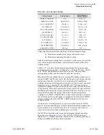
Table 4.20
Volts Per Hertz Settings
Setting Prompt
Setting Range
Setting Name :=
Factory Default
ENABLE V/HZ PROT
Y, N
E24 := Y
XFMR WDG CONN
DELTA, WYE
24WDG := WYE
LVL1 V/HZ PICKUP
100–200 %
24D1P := 105
LVL1 TIME DLY
0.04–400.00 s
24D1D := 1.00
LVL2 CURVE SHAPE
OFF, DD, ID, I, U
24CCS := ID
LVL2 INV-TM PU
100–200 %
24IP := 105
LVL2 INV-TM CURV
0.5, 1.0, 2.0
24IC := 2.0
LVL2 INV-TM FCTR
0.1–10.0 s
24ITD := 0.1
LVL2 PICKUP 2
101–200 %
24D2P2 := 176
LVL2 TIME DLY 2
0.04–400.00 s
24D2D2 := 3.00
LVL2 RESET TIME
0.00–400.00 s
24CR := 240.00
24 ELEM TRQ-CNTRL
SEL
OGIC
24TC := 1
Summary of Contents for SEL-787
Page 1: ...20081022 SEL 787 Transformer Protection Relay Instruction Manual PM787 01 NB ...
Page 6: ...This page intentionally left blank ...
Page 12: ...This page intentionally left blank ...
Page 18: ...This page intentionally left blank ...
Page 78: ...This page intentionally left blank ...
Page 206: ...This page intentionally left blank ...
Page 280: ...This page intentionally left blank ...
Page 334: ...This page intentionally left blank ...
Page 376: ...This page intentionally left blank ...
Page 388: ...This page intentionally left blank ...
Page 474: ...This page intentionally left blank ...
Page 508: ...This page intentionally left blank ...

