H.6
SEL-787 Relay
Instruction Manual
Date Code 20081022
Synchrophasors
Settings for Synchrophasors
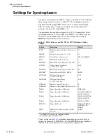
PHDATAV and VCOMP
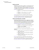
PHDATAV selects which voltage synchrophasors to include in the data packet.
Consider the burden on your synchrophasor processor and offline storage
requirements when deciding how much data to transmit. This setting is one of
six settings that determine the minimum port SPEED necessary to support the
synchrophasor data packet rate and size—see
for detailed information.
➤
PHDATAV := V1 will transmit only positive-sequence voltage,
V
1
➤
PHDATAV := ALL will transmit V
1
, V
A
, V
B
, and V
C
➤
PHDATAV := NA will not transmit any voltages
describes the order of synchrophasors inside the data packet.
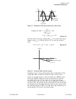
The VCOMP setting allows correction for any steady-state voltage phase
errors (from the potential transformers or wiring characteristics). See
Synchrophasor Measurement on page H.2
for details on this setting.
PHDATAI, PHCURR, IW1COMP, and IW2COMP
PHDATAI and PHCURR select which current synchrophasors to include in
the data packet. Consider the burden on your synchrophasor processor and
offline storage requirements when deciding how much data to transmit. These
settings are two of the sixsettings that determine the minimum port SPEED
necessary to support the synchrophasor data packet rate and size—see
Communications Bandwidth on page H.12
for detailed information.
➤
PHDATAI := I1 will transmit only positive-sequence current, I
1
➤
PHDATAI := ALL will transmit I
1
, I
A
, I
B
, and I
C
for the
Windings selected by PHCURR
➤
PHDATAI := NA will not transmit any currents
PHCURR selects the source current(s) for the synchrophasor data selected by
PHDATAI.
➤
PHCURR := IW1 uses the currents measured on the IAW1,
IBW1, and ICW1 inputs
➤
PHCURR := IW2 uses the currents measured on the IAW2,
IBW2, and ICW2 inputs
➤
PHCURR:= BOTH uses the currents measured on both the
I_W1 inputs and I_W2 inputs
describes the order of synchrophasors inside the data packet.
The IW1COMP and IW2COMP settings allow correction for any steady-state
phase errors (from the current transformers or wiring characteristics). See
Synchrophasor Measurement on page H.2
for details on these settings.
Summary of Contents for SEL-787
Page 1: ...20081022 SEL 787 Transformer Protection Relay Instruction Manual PM787 01 NB ...
Page 6: ...This page intentionally left blank ...
Page 12: ...This page intentionally left blank ...
Page 18: ...This page intentionally left blank ...
Page 78: ...This page intentionally left blank ...
Page 206: ...This page intentionally left blank ...
Page 280: ...This page intentionally left blank ...
Page 334: ...This page intentionally left blank ...
Page 376: ...This page intentionally left blank ...
Page 388: ...This page intentionally left blank ...
Page 474: ...This page intentionally left blank ...
Page 508: ...This page intentionally left blank ...

