4.11
Date Code 20081022
Instruction Manual
SEL-787 Relay
Protection and Logic Functions
Basic Protection
Selecting Y for E87 enables differential element settings.
When a value is entered in the MVA setting (i.e., MVA is not set to “OFF”),
the relay uses the MVA, winding voltage, CT ratio, and CT connection
settings (see
) you have entered and automatically calculates the
TAP1 and TAP2 values. You can also directly enter tap values when
MVA := OFF. TAP
MAX
/TAP
MIN
must be less than or equal to 7.5.
Set the operating current level O87P at a minimum for increased sensitivity,
but high enough to avoid operation because of steady-state CT error and
transformer excitation current. TAP • O87P must be greater than or equal to
0.1 • INOM for each tap value.
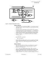
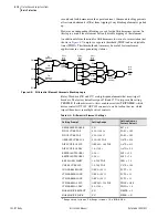
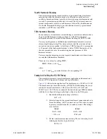
The SEL-787 includes a differential current alarm feature. Set the 87AP level
above the highest expected differential current under normal operations
(typically lower than O87P setting) and a security delay 87AD. See
for the logic diagram of this feature. Assertion of Relay Word bit 87AT
indicates a problem in the differential current circuit (e.g., open CT). You
must program the 87AT bit to take appropriate action (alarm, display message,
SER, etc.) as desired.
Figure 4.6
Differential Current Alarm Logic Diagram
Use the restraint slope percentage settings to discriminate between internal
and external faults. Set SLP1 or SLP2 to accommodate current differences
from power transformer tap-changer, CT saturation, CT errors, and relay error.
A two-slope, or variable-percentage differential application, improves
sensitivity in the region where CT error is less and increases security in the
high-current region where CT error is greater. We must define both slopes, as
well as the slope 1 limit or point IRS1, where SLP1 and SLP2 intersect. If you
want a single slope characteristic, set both SLOPE1 and SLOPE2 to the
desired slope value.
The purpose of the instantaneous unrestrained current element is to react
quickly to very heavy current levels that clearly indicate an internal fault. Set
the pickup level U87P to about 10 times tap. The unrestrained differential
element only responds to the fundamental frequency component of the
differential operating current. It is unaffected by the SLP1, SLP2, IRS1,
PCT2, or PCT5 settings. Thus, you must set the element pickup level high
enough so as not to react to large inrush currents.
Energization of a transformer causes a temporary large flow of magnetizing
inrush current into one terminal of a transformer, without the other terminal
seeing this current. Thus, it appears as a differential current that could cause
improper relay operation. Magnetizing inrush currents contain greater
amounts of even-harmonic current than do fault currents. This even-harmonic
current can be used to identify the inrush phenomenon and to prevent relay
misoperation. The SEL-787 measures the amount of second-harmonic and
fourth-harmonic currents flowing in the transformer. You can set the relay to
block the percentage restrained differential element if the ratio of second-
harmonic and/or fourth-harmonic current to fundamental current (IF2/IF1,
IF4/IF1) is greater than the PCT2 or PCT4 setting respectively. Also, the
87AP
(setting)
87AD
0
IOP1
_
+
87AT
87AP
AP2
AP3
AP1
Relay
Word
Bits
Summary of Contents for SEL-787
Page 1: ...20081022 SEL 787 Transformer Protection Relay Instruction Manual PM787 01 NB ...
Page 6: ...This page intentionally left blank ...
Page 12: ...This page intentionally left blank ...
Page 18: ...This page intentionally left blank ...
Page 78: ...This page intentionally left blank ...
Page 206: ...This page intentionally left blank ...
Page 280: ...This page intentionally left blank ...
Page 334: ...This page intentionally left blank ...
Page 376: ...This page intentionally left blank ...
Page 388: ...This page intentionally left blank ...
Page 474: ...This page intentionally left blank ...
Page 508: ...This page intentionally left blank ...

