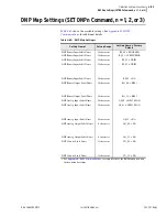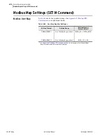
4.107
Date Code 20081022
Instruction Manual
SEL-787 Relay
Protection and Logic Functions
Report Settings (SET R Command)
To use the automatic deletion and reinsertion function, proceed with the
following steps:
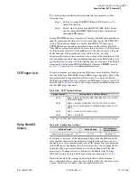
Step 1. Set Report setting ESERDEL (Enable SER Delete) to Y to
enable this function.
Step 2. Select values for the setting SRDLCNT (SER Delete Count)
and the setting SRDLTIM (SER Delete Time) that mask the
chattering SER element.
Setting SRDLTIM declares a time interval during which the relay qualifies an
input by comparing the changes of state of each input against the SRDLCNT
setting. When an item changes state more than SRDLCNT times in an
SRDLTIM interval, the relay automatically removes these Relay Word bits
from SER recording. Once deleted from recording, the item(s) will be ignored
for the next nine intervals. At the ninth interval, the chatter criteria will again
be checked and, if the point does not exceed the criteria, it will be
automatically reinserted into recording at the starting of the tenth interval. The
user can enable or disable the auto-deletion function via the SER settings. Any
auto-deletion notice entry will be lost during changes of settings. The deleted
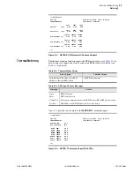
items can be viewed in the SER Delete Report (Command
SER D
—refer to
for additional information).
SER Trigger Lists
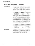
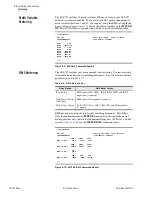
To capture element state changes in the SER report, enter the Relay Word bit
into one of the four SER (SER1 through SER4) trigger equations. Each of the
four programmable trigger equations allows entry of as many as 24 Relay
Word bits separated by spaces or commas; the SER report accepts a total of 96
Relay Word bits.
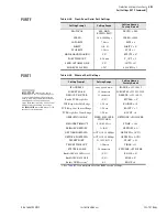
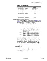
shows the settings prompt and default settings for
the four SER trigger equations.
Relay Word Bit
Aliases
To simplify your review of the information displayed in the SER record, the
relay provides the Alias setting function. Using the Alias settings, you can
change the way relay elements listed in the SER settings above are displayed
in the SER report. In addition, the Alias settings allow you to change the text
displayed when a particular element is asserted and deasserted. The relay
permits up to 20 unique aliases, as defined by the Enable Alias Settings
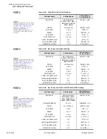
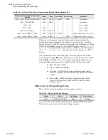
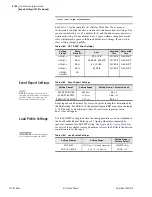
(EALIAS) setting. Factory default alias settings are shown in
Define the enabled alias settings by entering the Relay Word bit name, a
space, the desired alias, a space, the text to display when the condition asserts,
a space, and the text to display when the condition deasserts.
Table 4.60
SER
a
Trigger Settings
a
Use up to 24 Relay Word elements separated by spaces or commas for each setting.
Setting Prompt
Setting Name := Factory Default
SER1
SER1 := IN101 IN102 PB01 PB02 PB03 PB04 52A1 52A2 TRIP1
TRIP2 TRIPXFMR
SER2
SER2 := ORED51T ORED50T 87U 87R 27P1T 27P2T 59P1T
59P2T 59Q1T 59Q2T 3PWR1T 3PWR2T REF1F 24D1T 24C2T
RTDT
SER3
SER3 := 81D1T 81D2T 81D3T 81D4T
SER4
SER4 := SALARM
Table 4.61
Enable Alias Settings
Setting Prompt
Setting Range
Setting Name =
Factory Default
Enable ALIAS Settings (N, 1–20)
N, 1–20
EALIAS = 4
Summary of Contents for SEL-787
Page 1: ...20081022 SEL 787 Transformer Protection Relay Instruction Manual PM787 01 NB ...
Page 6: ...This page intentionally left blank ...
Page 12: ...This page intentionally left blank ...
Page 18: ...This page intentionally left blank ...
Page 78: ...This page intentionally left blank ...
Page 206: ...This page intentionally left blank ...
Page 280: ...This page intentionally left blank ...
Page 334: ...This page intentionally left blank ...
Page 376: ...This page intentionally left blank ...
Page 388: ...This page intentionally left blank ...
Page 474: ...This page intentionally left blank ...
Page 508: ...This page intentionally left blank ...

