5.16
SEL-787 Relay
Instruction Manual
Date Code 20081022
Metering and Monitoring
Through-Fault Event Monitoring
Through-Fault
Element (TFE) Serial
Command
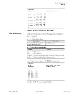
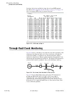
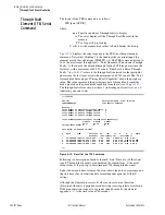
The format of the TFE command is as follows:
TFE [nnn A|P|C|R]
where:
displays the relay response to the TFE (no other parameters)
command. Notice that Winding 1 is the winding whose current inputs the
element uses in the calculations (THFLTD = 1). The TFE command lists up to
20 of the most recent through-faults. "Total Number of Transformer Through
Faults:" is the sum of the detected through faults of all three phases since the
last reset, with a maximum of 65,535 counts. "Number of n Phase Through
Faults:" (n = A, B, C) refers to the through faults detected for that particular
phase since the last reset, also with a maximum of 65,535 counts. The "Total
Accumulated Percentage of Through Fault Capability" shows the per phase
value. The value represents the percent amount of through fault capability
used up based on the per unitized capability from the curve of
.
The through-fault alarm state is either a 1 (indicating an alarm state), or a 0
(indicating a normal state).
=>>
TFE <Enter>
SEL-787 Date: 04/03/2008 Time: 15:24:02
TRNSFRMR RELAY Time Source: Internal
Winding 1
Total Number of Transformer Through Faults: 4
Total Number of A Phase Through Faults: 2
Total Number of B Phase Through Faults: 1
Total Number of C Phase Through Faults: 1
Total Accumulated Percentage of Through Fault Capability:
A-Phase B-Phase C-Phase
95.97 60.00 60.00
Through Fault Alarm: 0 0 0
Last Reset: 04/03/2008 15:16:27
# DATE TIME Duration IA IB IC A B C Alarm
(seconds) (max primary kA) (Increment %)
1 04/03/2008 15:23:37.102 19.983 1.99 0.00 0.00 35.97 0.00 0.00
2 04/03/2008 15:20:23.256 1.663 0.00 0.00 3.28 0.00 0.00 50.94 ABC
3 04/03/2008 15:20:19.918 1.675 0.00 6.37 0.00 0.00 99.99 0.00 AB
4 04/03/2008 15:20:16.596 1.650 1.99 0.00 0.00 2.97 0.00 0.00 A
=>>
Figure 5.19
Result of the TFE Command
Following is a description of each column (#, Date, Time, etc.) of the event
report. Through-faults events are numbered (# column) from 1 (the most
recent event, at the top) up to a maximum of 500 through-faults events.
Under the date and time columns, the event shows the date of occurrence and
the start time of each event (the date format depends upon the DATE_F
setting).
Although the element processes all values each cycle, event duration
(Duration column) is reported in seconds with processing interval resolution.
If the event duration is equal to or greater than 60 seconds, the element
appends a “+” to the time value of 60 seconds.
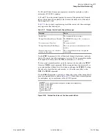
nnn Specifies number of through faults to display.
A The relay displays all the Through Fault Records in the
memory.
P Use to specify pre-loading
C or R Sets the accumulated values to 0 and deletes the history.
Summary of Contents for SEL-787
Page 1: ...20081022 SEL 787 Transformer Protection Relay Instruction Manual PM787 01 NB ...
Page 6: ...This page intentionally left blank ...
Page 12: ...This page intentionally left blank ...
Page 18: ...This page intentionally left blank ...
Page 78: ...This page intentionally left blank ...
Page 206: ...This page intentionally left blank ...
Page 280: ...This page intentionally left blank ...
Page 334: ...This page intentionally left blank ...
Page 376: ...This page intentionally left blank ...
Page 388: ...This page intentionally left blank ...
Page 474: ...This page intentionally left blank ...
Page 508: ...This page intentionally left blank ...

