4.8
SEL-787 Relay
Instruction Manual
Date Code 20081022
Protection and Logic Functions
Basic Protection
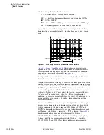
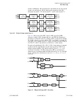
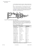
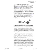
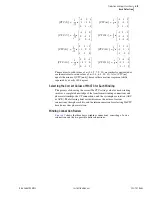
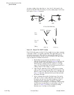
shows how the differential element quantities are used to generate
the unrestrained 87U
n
(87U1, 87U2, 87U3) and restrained 87R
n
/87HR
n
(87R1, 87R2, 87R3, 87HR1, 87HR2, 87HR3) elements.
Unrestrained elements (87U1, 87U2, and 87U3) compare the IOP quantity to
a setting value (U87P), typically about 10 times TAP, and trip if this level is
exceeded. Elements 87U1, 87U2, and 87U3 are combined to form element
87U as shown in the lower left corner of
. Harmonic blocking or
restraint is not performed on the unrestrained elements. Use these elements to
protect your transformer bushings and end windings while maintaining
security for inrush and through-fault conditions. Operating current elements
87O
n
(87O1, 87O2, 87O3) are not available as Relay Word bits.
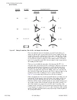
Restrained elements (87R1, 87R2, and 87R3) determine whether the IOP
quantity is greater than the restraint quantity using the differential
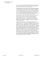
characteristic shown in
. This characteristic is modified by
increasing the restraint current as a function of the second- and fourth-
harmonic content in the input currents for the harmonic restraint elements
(87HR1, 87HR2, and 87HR3). Set HRSTR = Y to activate the harmonic
restraint element 87HR.
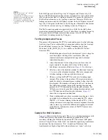
In element 87R
n
, for example, the IOP
n
and IRT
n
quantities determine
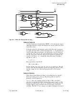
whether the relay trips. The logic enclosed within the dotted line of
implements the
characteristic. The differential element calculates a
threshold as a function of IRT
n
. IOP
n
must exceed this threshold to assert
87R
n
. The function uses the SLP1, SLP2, and IRS1 setting values, along with
IRT
n
, to calculate the IOP value. The relay uses SLOPE2 in place of SLOPE1
when the Relay Word bit INRn is asserted. This feature provides a high
security mode of operation for 10 cycles when the transformer is energized.
The differential element decision logic compares the calculated value, denoted
f(IRT
n
), to the actual IOP
n
. If IOP
n
is greater, one input of the AND gate at
the right receives a logic 1. Comparison of IOP
n
with the O87P setting
determines the second AND input. If IOP
n
is greater than O87P, the bit 87O
n
asserts. The AND gate condition then is satisfied, and Relay Word bit 87R
n
asserts, indicating operation of the restrained differential element,
n
. This does
not, as yet, produce a trip. The relay still needs the results of the harmonic
blocking decision logic, which is described later.
Summary of Contents for SEL-787
Page 1: ...20081022 SEL 787 Transformer Protection Relay Instruction Manual PM787 01 NB ...
Page 6: ...This page intentionally left blank ...
Page 12: ...This page intentionally left blank ...
Page 18: ...This page intentionally left blank ...
Page 78: ...This page intentionally left blank ...
Page 206: ...This page intentionally left blank ...
Page 280: ...This page intentionally left blank ...
Page 334: ...This page intentionally left blank ...
Page 376: ...This page intentionally left blank ...
Page 388: ...This page intentionally left blank ...
Page 474: ...This page intentionally left blank ...
Page 508: ...This page intentionally left blank ...

