4
SEL-300G Relay
Quick-Start Guide
Date Code 20170804
Relay Commissioning Procedure
Commissioning Procedure
polarity marks, review your dc wiring diagrams to ensure that
even-numbered terminals are applied at a higher potential than
odd-numbered terminals in their dc circuits.
Step 6. In preparation to energize and set the relay, remove ac signals
from the relay and isolate its tripping contacts.
Step 7. Energize the relay by closing the dc breaker or installing the dc
fuses. Within a moment of energizing the relay, the green
enable LED (
EN
) on the front panel should illuminate, and the
relay self-test ALARM contact (A15, A16) should open (type b
contact).
Step 8. Connect the PC to the relay using the appropriate serial cable.
Refer to
for typical cable numbers. These cables are
available directly from SEL or you can build your own cable
using the cable pinout shown in the SEL-5801 Cable Selector
Software. This software is available from SEL, or can be
downloaded free of charge from the SEL website at http://
www.selinc.com.
Serial Port 1 on all the SEL-300G models is an EIA-485 port
(4-wire). The Serial Port 1 plug-in connector accepts wire size
AWG 24 to 12. Strip the wires 0.31 inches (8 mm) and install
with a small slotted-tip screwdriver. Serial Port 1 connector has
extra positions for IRIG-B time-code signal input.
All EIA-232 ports accept 9-pin D-subminiature male
connectors. Port 2 on all the SEL-300G models also accepts
demodulated IRIG-B time-code signal input.
Refer to
for a list of cables available from SEL for
various communication applications.
For example, to connect any EIA-232 port to the 9-pin male
connector on a laptop computer, order cable number C234A
and specify the length needed (standard length is eight feet).
For connecting devices at distances over 100 feet, SEL offers
fiber-optic transceivers. The SEL-2800 family of transceivers
provides fiber-optic links between devices for electrical
isolation and long-distance signal transmission. Contact SEL
for further information on these products.
NOTE:
Listing of devices not
manufactured by SEL in Table 1 is for
the convenience of our customers.
SEL does not specifically endorse or
recommend such products, nor does
SEL guarantee proper operation of
those products, or the correctness of
connections, over which SEL has no
control.
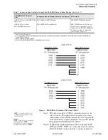
Table 1
Communication Cables to Connect the SEL-300G Relay to Other Devices
(Sheet 1 of 2)
SEL-300G EIA-232 Serial
Ports
Connect to Device (Gender Refers to the Device)
SEL Cable #
all EIA-232 ports
PC, 25-Pin Male (DTE
a
)
C227A
all EIA-232 ports
Laptop PC, 9-Pin Male (DTE
)
C234A
all EIA-232 ports
SEL Communications Processors without IRIG-B
C272A
2
SEL Communications Processors with IRIG-B
C273A
all EIA-232 ports
SEL-PRTU
C231
2
SEL-IDM, Ports 2 through 11
C254 + C257
2
b
Dial-up modem, 5 Vdc Powered
C220
all EIA-232 ports
Standard modem, 25-Pin Female (DCE
c
)
C222
all EIA-232 ports
RFL-9660
C245A
Summary of Contents for SEL-300G
Page 1: ...20170804 SEL 300G Multifunction Generator Relay Quick Start Guide PM300GQS 01 ...
Page 4: ...This page intentionally left blank ...
Page 6: ...This page intentionally left blank ...
Page 8: ...This page intentionally left blank ...
Page 12: ...This page intentionally left blank ...
Page 55: ......
Page 56: ......


