background image

20

SEL-300G Relay

Quick-Start Guide

Date Code 20170804

Relay Mounting

Secondary Functions

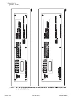
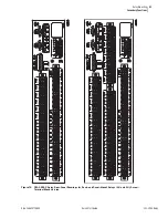
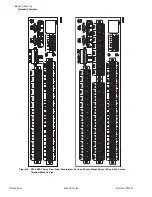
Figure 12

SEL-300G Relay Front-Panel Drawings for Panel-Mount Relays ((2U and 3U), Screw-Terminal Block 
and Connectorized Versions

Summary of Contents for SEL-300G

Page 1: ...20170804 SEL 300G Multifunction Generator Relay Quick Start Guide PM300GQS 01 ...

Page 2: ...ents Schweitzer Engineering Laboratories Inc reserves all rights and benefits afforded under federal and international copyright and patent laws in its products including without limitation software firmware and documentation The information in this document is provided for informational use only and is subject to change without notice Schweitzer Engineering Laboratories Inc has approved only the ...

Page 3: ...12 Front Panel Pushbutton Operation 14 Overview 14 Primary Functions 14 Front Panel Password Security 15 Secondary Functions 16 Relay Mounting 18 Circuit Board Jumpers 29 Accessing the Relay Main Board All Models and Extra I O Board Models 0300G_1 and 0300G_Y 29 Output Contact Jumpers 32 Extra Alarm Output Contact Control Jumper 33 Password and Breaker Jumpers 34 EIA 232 Serial Port Voltage Jumper...

Page 4: ...This page intentionally left blank ...

Page 5: ...fers 11 Table 5 Serial Port Command Summary 12 Table 6 Output Contact Jumpers and Corresponding Output Contacts 33 Table 7 Extra Alarm Output Contacts and Corresponding Controlling Jumpers 33 Table 8 Required Position of Jumper JMP23 for Desired Output Contact OUT107 Operation All Models 33 Table 9 Password and Breaker Jumper Positions for Standard Relay Shipments 34 Table 10 Password and Breaker ...

Page 6: ...This page intentionally left blank ...

Page 7: ...ays 2U and 3U Screw Terminal Block Version 21 Figure 14 SEL 300G1 Relay Rear Panel Drawings for Rack and Panel Mount Relays 2U and 3U Screw Terminal Block Version 22 Figure 15 SEL 300G2 Relay Rear Panel Drawings for Rack and Panel Mount Relays 2U and 3U Screw Terminal Block Version 23 Figure 16 SEL 300G3 Relay Rear Panel Drawings for Rack and Panel Mount Relays 2U and 3U Screw Terminal Block Versi...

Page 8: ...This page intentionally left blank ...

Page 9: ...simply contact the factory using the information provided in Factory Assistance The SEL 300G Relay Instruction Manual contains additional details on relay operation and settings calculations Safety Information The SEL 300G Relay Quick Start Installation Guide does not cover all of the possible conditions or circumstances that can occur during the installation of the SEL 300G If you need additional...

Page 10: ...la tension d alimentation nominale est 24 48 VCC Une perte de fonctionnement du relais et un bris permanent de l alimentation résulteraient de l application d une polarité CC inversée sur un relais avec tension nominale de 24 48 VCC CAUTION Standard SEL relay output contacts are rated to make and carry trip coil current but are not rated to interrupt trip coil current Do not exceed the contact int...

Page 11: ...ute responsabilité pour tout dommage résultant de cet accès non autorisé WARNING Use of this equipment in a manner other than specified in this manual can impair operator safety safeguards provided by this equipment AVERTISSEMENT L utilisation de cet appareil suivant des procédures différentes de celles indiquées dans ce manuel peut désarmer les dispositifs de protection d opérateur normalement ac...

Page 12: ...This page intentionally left blank ...

Page 13: ...m with your standard practices and the operating and commissioning guidelines published by the generator and prime mover manufacturers Required Equipment SEL 300G Relay installed and connected according to your protection design PC with serial port terminal emulation software and serial communication cable for relay setting entry SEL 300G Settings Sheets filled out with settings appropriate to you...

Page 14: ...ts STEP 13 Verify Contact Input Operation STEP 12 Verify AC Wiring See Fig 3 4 STEP 11 Enter Relay Settings STEP 10 Configure Emulation Software STEP 9 Run Emulation Software STEP 14 Verify Contact Output Operation STEP 18 Operate Generator at No Load STEP 17 Connect Relay for Tripping Duty STEP 19 Operate Generator at 10 Load Record No Load Third Harmonic Voltages STEP 23 Clear Relay Data Buffers...

Page 15: ... is important because the SEL 300G 24 48 Vdc power supply is polarity sensitive Figure 2 DC Supply Polarity Continuity Checks Step 5 Select models of the SEL 300G_1 or SEL 300G_Y are equipped with polarity sensitive high current interrupting output contacts When the relay is so equipped it will have polarity marks above even numbered terminals in the B series such as B02 B04 etc If your relay outp...

Page 16: ...pin D subminiature male connectors Port 2 on all the SEL 300G models also accepts demodulated IRIG B time code signal input Refer to Table 1 for a list of cables available from SEL for various communication applications For example to connect any EIA 232 port to the 9 pin male connector on a laptop computer order cable number C234A and specify the length needed standard length is eight feet For co...

Page 17: ...05Z010VVX0003 3 meters d All EIA 232 ports with SEL 2812MR transceiver SEL 2664 Field Ground Module SEL C805 Multimode 200 µm core diameter fiber optic cable with ST connectors or SEL C807 Multimode 62 5 µm core diameter fiber optic cable with ST connectors a Data Terminal Equipment b A corresponding main board jumper must be installed to power the dial up modem with 5 Vdc 0 5 A limit from the SEL...

Page 18: ...efer to Table 8 and Table 9 for Password jumper information The factory default passwords for Access Levels 1 B 2 and C are At the Access Level 0 prompt enter the ACC command ACC Enter If the Password jumper is not in place the relay asks for the Access Level 1 password to be entered Password The relay is shipped with the default Access Level 1 password shown above Enter the default password and p...

Page 19: ...s Enter to accept the existing setting Editing keystrokes are shown in Table 2 The relay checks each entry to ensure that it is within the setting range If it is not an Out of Range message is generated and the relay prompts for the setting again When all the settings are entered the relay displays the new settings and prompts for approval to enable them Answer Y Enter to enable the new settings I...

Page 20: ...ctly to the relay however this does not verify the accuracy of the wiring in the protection cabinet Apply rated ac voltage 67 V1n 120 V11 and current 1 A or 5 A to the relay phase voltage and current inputs Set the test source phase angles to supply no phase difference between phase voltage and phase current If a three phase test source is used set the source phase angles as shown in Figure 4 Figu...

Page 21: ...ities are displayed in primary units Step 13 Verify optoisolated input connections Use the front panel OTHER pushbutton and the TAR function to cause the relay to display Relay Word Row 31 on the relay front panel LEDs Apply rated dc voltage to the individual relay optoisolated input circuits As you apply dc voltage to each input its label will appear in the LCD display and its LED will illuminate...

Page 22: ...phase angles Voltage magnitudes should be nearly equal Voltage phase angles should be balanced and have proper phase rotation The positive sequence voltage magnitude V1 should be nearly equal to VA VB and VC or VAB 1 73 The negative sequence voltage magnitude V2 and zero sequence voltage magnitude 3V0 if shown should both be nearly zero After correcting any problems indicated by the phase and sequ...

Page 23: ...n Manual Using the serial port SET command enter the newly calculated 64G element settings and add 64G2T to tripping SELOGIC control equations If desired perform 64G protection element tests to verify the element performance with the new settings Step 23 To prepare the relay for operation it is usually helpful to clear several of the relay data buffers This prevents data generated during installat...

Page 24: ...r to operate output contacts or change the active setting group The Access Level 2 commands allow the user to change relay settings The Access Level C restricted access level should be used under the direction of SEL only If you are communicating at a higher access level you may also use serial port commands from lower access levels The commands are shown in upper case letters but they can also be...

Page 25: ... check reports 300G2 300G3 1 TAR Display relay element status OTHER 1 TIM View change time OTHER 1 TRI Trigger an event report B CLO Close breaker B GRO n Change active setting group GROUP B OPE Open breaker B PUL Pulse output contact CNTRL 2 BRE n Preload reset breaker wear OTHER 2 CAL Go to Access Level C Access Level C is reserved for SEL use only 2 CON Control remote bit 2 COP Copy setting gro...

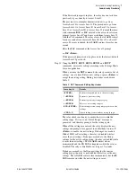
Page 26: ...resent selected function metering is exited press EXIT pushbutton or the display goes back to the default display after no front panel activity for a settable time period Figure 6 SEL 300G Front Panel Pushbuttons Overview Primary Functions Note in Figure 7 and Figure 8 that the front panel pushbutton primary functions correspond to serial port commands both retrieve the same information or perform...

Page 27: ...ECT pushbutton once the correct Access Level B or Access Level 2 password is ready to enter The factory default passwords for Access Level 1 B and 2 are listed at the front of this guide under Step 10 of the Relay Commissioning Procedure TARGET RESET LAMP TEST METER EVENTS STATUS STA HIS MET MET D MET E MET M MET RD MET RE MET RM MET RP MET DIF MET T Access Level 1 Front panel pushbutton functions...

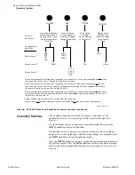
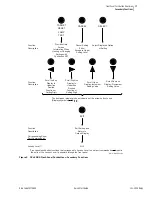
Page 28: ...cription Corresponding Serial Port Commands at Access Level 11 1 Front panel pushbutton functions that correspond to Access Level 1 serial port commands do not require the entry of the Access Level 1 password through the front panel 2 Front panel pushbutton functions that correspond to Access Level B serial port commands do require the entry of the Access Level B or Access Level 2 passwords throug...

Page 29: ...n or Setting Digit Scroll Right on Display to Underline Desired Function or Setting Digit Scroll Up on Display Increment Setting Value Scroll Down on Display Decrement Setting Value Function Description Select Displayed Option or Setting SELECT Exit Entirely and Return to Default Display EXIT QUI Function Description Corresponding Serial Port Commands at Access Level 1 Front panel pushbutton funct...

Page 30: ...18 SEL 300G Relay Quick Start Guide Date Code 20170804 Relay Mounting Secondary Functions Relay Mounting Figure 10 SEL 300G Dimensions and Panel Mount Cut Out ...

Page 31: ... Code 20170804 Quick Start Guide SEL 300G Relay Relay Mounting Secondary Functions Figure 11 SEL 300G Relay Front Panel Drawings for Rack Mount Relays 2U and 3U Screw Terminal Block and Connectorized Versions ...

Page 32: ...300G Relay Quick Start Guide Date Code 20170804 Relay Mounting Secondary Functions Figure 12 SEL 300G Relay Front Panel Drawings for Panel Mount Relays 2U and 3U Screw Terminal Block and Connectorized Versions ...

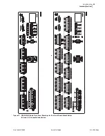
Page 33: ... Date Code 20170804 Quick Start Guide SEL 300G Relay Relay Mounting Secondary Functions Figure 13 SEL 300G0 Relay Rear Panel Drawings for Rack and Panel Mount Relays 2U and 3U Screw Terminal Block Version ...

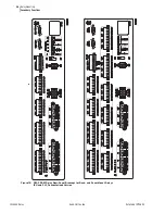
Page 34: ... SEL 300G Relay Quick Start Guide Date Code 20170804 Relay Mounting Secondary Functions Figure 14 SEL 300G1 Relay Rear Panel Drawings for Rack and Panel Mount Relays 2U and 3U Screw Terminal Block Version ...

Page 35: ... Date Code 20170804 Quick Start Guide SEL 300G Relay Relay Mounting Secondary Functions Figure 15 SEL 300G2 Relay Rear Panel Drawings for Rack and Panel Mount Relays 2U and 3U Screw Terminal Block Version ...

Page 36: ... SEL 300G Relay Quick Start Guide Date Code 20170804 Relay Mounting Secondary Functions Figure 16 SEL 300G3 Relay Rear Panel Drawings for Rack and Panel Mount Relays 2U and 3U Screw Terminal Block Version ...

Page 37: ...25 Date Code 20170804 Quick Start Guide SEL 300G Relay Relay Mounting Secondary Functions Figure 17 SEL 300G0 Relay Rear Panel Drawings for Rack and Panel Mount Relays 2U and 3U Connectorized Version ...

Page 38: ...26 SEL 300G Relay Quick Start Guide Date Code 20170804 Relay Mounting Secondary Functions Figure 18 SEL 300G1 Relay Rear Panel Drawings for Rack and Panel Mount Relays 2U and 3U Connectorized Version ...

Page 39: ...27 Date Code 20170804 Quick Start Guide SEL 300G Relay Relay Mounting Secondary Functions Figure 19 SEL 300G2 Relay Rear Panel Drawings for Rack and Panel Mount Relays 2U and 3U Connectorized Version ...

Page 40: ...28 SEL 300G Relay Quick Start Guide Date Code 20170804 Relay Mounting Secondary Functions Figure 20 SEL 300G3 Rear Panel Drawings for Rack and Panel Mount Relays 2U and 3U Connectorized Version ...

Page 41: ...the circuit board you wish to remove by loosening the screws on either end of each connector Removal of the extra I O board also requires removal of the main board because the LCD on the main board is in the way Step 6 On screw terminal block models disconnect the ribbon cables from the board s Grasp the drawout assembly of the board and pull the assembly from the relay chassis In models 0300G_1 a...

Page 42: ...ain Board All Models ALARM OUT106 OUT105 OUT104 OUT107 OUT103 OUT102 OUT101 OPTOISOLATED INPUTS OUTPUT CONTACTS A B JMP29 DWG M300G096 A B JMP28 A B JMP27 A B JMP26 A B JMP25 A B JMP24 A B JMP22 A B JMP21 JM P2 3 SERIAL PORT 1 EIA 485 SERIAL PORT 2 EIA 232 SERIAL PORT 3 EIA 232 JMP1 J1 JMP2 JMP6 A B C D µC U46 SERIAL PORT F EIA 232 R131 LEDs PUSHBUTTONS POWER I O CONNECTOR ANALOG CONNECTOR LCD CON...

Page 43: ...nnector and Major Component Locations on the SEL 300G Extra I O Board Models 0300G_1 Screw Terminal Block Version A B A A A A A B A B OUT212 OUT211 OUT210 OUT209 OUT207 OUT206 OUT205 JMP17 JMP19 JMP18 B B B B A OUT208 B A B OUT204 A B OUT203 A B OUT202 OPTOISOLATED INPUTS OUTPUT CONTACTS A B POWER I O CONNECTOR JMP20 JMP21 JMP22 JMP23 JMP24 JMP25 JMP26 JMP27 JMP28 OUT201 DWG M300G095 ...

Page 44: ...ey control The referenced figures show the exact location and correspondence With a jumper in the A position the corresponding output contact is an a type output contact An a type output contact is open when the output contact coil is de energized and closed when the output contact coil is energized With a jumper in the B position the corresponding A B A A A OUT212 OUT211 OUT210 OUT209 OUT207 OUT2...

Page 45: ...board see Table 7 The position of the jumper controls the operation of the output contact next to the dedicated ALARM output contact With the jumper in one position the output contact operates regularly With the jumper in the other position the output contact is driven by the same signal that operates the dedicated ALARM output contact see Table 8 Table 6 Output Contact Jumpers and Corresponding O...

Page 46: ...ts The 5 Vdc is rated at 0 5 A maximum for each port In a standard relay shipment the jumpers are OFF removed not in place so that the 5 Vdc is not connected to Pin 1 on the corresponding EIA 232 serial ports Put the jumpers ON in place so that the 5 Vdc is connected to Pin 1 on the corresponding EIA 232 serial ports Table 9 Password and Breaker Jumper Positions for Standard Relay Shipments Passwo...

Page 47: ... 125 Vdc or 125 Vac Range 38 200 Vdc or 85 140 Vac Burden 25 W 24 48 Vdc Range 18 60 Vdc polarity dependent Burden 25 W Output Contacts Standard Make 30 A Carry 6 A 70 C 4 A 85 C 1 s Rating 50 A MOV 270 Vac 360 Vdc 40 J Pickup Time 5 ms Dropout Time 8 ms typical Breaking Capacity 10 000 operations 24 V 0 75 A L R 40 ms 48 V 0 50 A L R 40 ms 125 V 0 30 A L R 40 ms 250 V 0 20 A L R 40 ms Cyclic Capa...

Page 48: ...900 MHz and 1 89 GHz Electrostatic Discharge IEC 60255 22 2 2008 IEC 61000 4 2 2008 IEEE C37 90 3 2001 Severity Level Contact Discharge 2 4 6 and 8 kV Air Discharge 2 4 8 and 15 kV Radiated Radio Frequency ENV 50140 1993 10 V m IEC 60255 22 3 2000 10 V m IEC 61000 4 3 1998 10 V m IEEE C37 90 2 1995 35 V m no keying test frequency elements accurate to 0 1 Hz Fast Transient Disturbance IEC 60255 22 ...

Page 49: ...nsient Angle Accuracy 1 8 slip 0 5 Directional Power Element 32 Two Definite Time Elements Setting Range 0 0015 to 3 000 pu Steady State Pickup Accuracy 0 0015 pu 2 of setting INOM 5 A VNOM 120 V PF 0 2 Pickup Time 25 ms at 60 Hz Max Definite Time Setting Range 0 01 400 00 s Maximum Definite Time Delay Accuracy 0 1 4 2 ms at 60 Hz Loss of Field Element 40 Two Mho Zones 5 A Model Zone 1 Offset 50 0...

Page 50: ...1 V SELOGIC Control Equation Time Delay Setting Range 0 00 3000 00 s Note Desired time delay may be added using SELOGIC control equation timers 100 Percent Stator Ground Protection 64G Neutral Fundamental Overvoltage 64G1 0 0 150 0 V Steady State Pickup Accuracy 5 0 1 V Pickup Time 25 ms at 60 Hz Max Definite Time Delay 0 00 400 00 s Maximum Definite Time Delay Accuracy 0 1 4 2 ms at 60 Hz Third H...

Page 51: ... Max Time Delays 0 00 400 00 s Maximum Definite Time Delay Accuracy 0 1 4 2 ms at 60Hz Optional RTD Elements Models Compatible With SEL 2600 Series RTD Module 12 RTD Inputs via SEL2600 Series RTD Module and SEL 2800 Fiber Optic Transceiver Monitor Winding Bearing Ambient or Other Temperatures PT100 NI100 NI120 and CU10 RTD Types Supported Field Selectable Trip Alarm and Ambient Load Current Bias S...

Page 52: ...rent 1 0 A 0 70 0 or 180 unity power factor 0 75 6 50 8 or 172 1 00 2 00 30 or 150 1 50 1 50 45 or 135 2 00 1 00 60 or 120 6 50 0 75 82 or 98 0 70 90 power factor 0 for phase current 1 0 A 0 35 0 or 180 unity power factor 0 40 6 00 8 or 172 0 75 1 50 30 or 150 1 00 1 00 45 or 135 1 50 0 75 60 or 120 6 00 0 40 82 or 98 0 35 90 power factor 0 Metering accuracy calculation example for currents IA IB ...

Page 53: ...cent remains on a single phase check the CT tap connections of the affected phase to verify that the relay is connected to the appropriate CT tap per the CTR and CTRD settings If mismatch remains on all three phases check the CTR and CTRD settings to ensure that they are correct per the actual CT ratio Date Installer RELAY ID RID TERMINAL ID TID CTR CTRD E87 TRCON CTCON With load applied to the re...

Page 54: ... AND TRCON GEN CTCON Y TRCON DABY CTCON DAB TRCON YDAB CTCON Y TRCON DACY CTCON DAC TRCON YDAC CTCON Y TRCON DABDAB CTCON Y TRCON DACDAC CTCON Y TRCON YY CTCON Y Then phase angles should be 180 apart Plot Phasors If E87 T AND TRCON GEN CTCON DAC TRCON DABY CTCON Y TRCON YDAC CTCON Y Then I87 should lead IW1 by 150 If E87 T AND TRCON GEN CTCON DAB TRCON DACY CTCON Y TRCON YDAB CTCON Y Then I87 shou...

Page 55: ......

Page 56: ......
Reviews: