29
Date Code 20170804
Quick-Start Guide
SEL-300G Relay
Circuit Board Jumpers
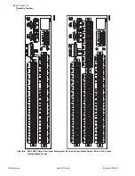
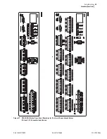
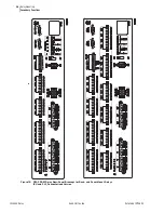
Accessing the Relay Main Board (All Models) and Extra I/O Board (Models 0300G_1 and 0300G_Y)
Circuit Board Jumpers
Accessing the Relay
Main Board (All
Models) and Extra I/O
Board (Models
0300G_1 and
0300G_Y)
To change circuit board jumpers or replace the clock battery on the relay main
board (or change output contact jumpers on the extra I/O board), refer to
,
and take the following steps:
Step 1. De-energize the relay. On Connectorized versions this can be
accomplished easily by removing the connector at rear-panel
terminals Z25 and Z26.
Step 2. Remove any cables connected to serial ports on the front and
rear panels.
Step 3. Loosen the six front-panel screws (they remain attached to the
front panel), and remove the relay front panel.
Step 4. Identify which drawout board needs to be changed. All
SEL-300G models have a main board in the top guides, and
Models 0300G_1 and 0300G_Y have an extra I/O board below
the main board. Each board corresponds to a row of rear-panel
screw-terminal blocks.
Step 5. On Connectorized versions, remove the rear-panel connectors
that correspond to the circuit board you wish to remove by
loosening the screws on either end of each connector. Removal
of the extra I/O board also requires removal of the main board
(because the LCD on the main board is in the way).
Step 6. On screw-terminal block models, disconnect the ribbon cables
from the board(s). Grasp the drawout assembly of the board,
and pull the assembly from the relay chassis. In models
0300G_1 and 0300G_Y, the extra I/O board directly below the
main board requires removal of the main board first (because
the LCD on the main board is in the way).
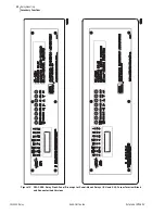
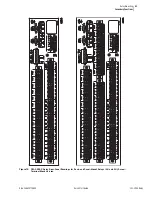
Step 7. Locate the jumper(s) or battery to be changed (refer to
). Change the jumper
position(s). Note that the output contact jumpers are soldered in
place.
Step 8. Slide the drawout assemblies into the relay chassis (main board
last). Reconnect the ribbon cables. Replace the relay front
panel and re-energize the relay. On Connectorized versions,
replace the power connector at rear-panel terminals Z25 and
Z26.
CAUTION
Equipment components are sensitive
to electrostatic discharge (ESD).
Undetectable permanent damage can
result if you do not use proper ESD
procedures. Ground yourself, your
work surface, and this equipment
before removing any cover from this
equipment. If your facility is not
equipped to work with these
components, contact SEL about
returning this device and related SEL
equipment for service.
Summary of Contents for SEL-300G
Page 1: ...20170804 SEL 300G Multifunction Generator Relay Quick Start Guide PM300GQS 01 ...
Page 4: ...This page intentionally left blank ...
Page 6: ...This page intentionally left blank ...
Page 8: ...This page intentionally left blank ...
Page 12: ...This page intentionally left blank ...
Page 55: ......
Page 56: ......


