background image

Table of Contents

SECTION VI

Paragraph

Title

Page

6-1.

Weight and Balance Characteristics . . . .

6-1

6-2.

Weight Limits and Balance Criteria . . . . .

6-8

6-3.

Equipment Removal or Installation . . . . .

6-8

6-4.

Longitudinal Weight and Balance

Determination . . . . . . . . . . . . .

6-12

6-5.

Lateral Weight and Balance Determination .

6-17

List of Figure

Figure

Title

Page

6-1.

Balance Diagram . . . . . . . . . . . . . .

6-3

6-2.

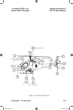
Station Diagram . . . . . . . . . . . . . .

6-5

6-3.

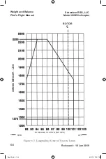
Longitudinal Center of Gravity Limits . . . .

6-6

6-4.

Lateral Center of Gravity Limits . . . . . . .

6-7

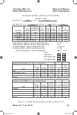
6-5.

Sample Weight and Balance Report . . . .

6-9

6-6.

Basic Weight and Balance Record . . . . .

6-11

6-7.

Fuel Buttline. . . . . . . . . . . . . . . . .

6-14

6-8.

Specific Weight of Fuels and Lubricants . .

6-19

List of Tables

Table

Title

Page

6-1.

Center of Gravity Limits . . . . . . . . . . .

6-2

6-2.

Weights and Longitudinal Moments -

Pilot, Passenger, Baggage . . . . . . . .

6-16

Weight and Balance

 Schweizer RSG, LLC.      

Model


269D


Helicopter

Pilot's Flight Manual

6-i

Reissued:


16

 Jan 2019 

Book 3.indd   137

8/4/19   1:25 PM

Summary of Contents for 269D

Page 1: ...ed to disclose or so use any information contained herein All rights reserved Any act in ation of applicable law may result in civil and criminal penalties Export Warning These commodities technical data or software are subject to the export control of either the International Traffic in Arms Regulations ITAR or the Export Administration Regulations EAR and cannot be exported without the prior aut...

Page 2: ...This page is intentionally left blank Pilot s Flight Manual Schweizer RSG LLC Model 269D Helicopter Fii Reissued 16 Jan 2019 Book 3 indd 2 8 4 19 1 25 PM ...

Page 3: ...ons 2 2 2 4 Multipurpose Utility Operations 2 4 2 5 Airspeed Limits 2 4 2 6 Rotor Speed Limits 2 4A 2 7 Weight Limitations 2 4A 2 8 Center of Gravity CG Envelope 2 6 2 9 Power Plant Limits Rolls Royce Model 250 C20W 2 9 2 10 Fuels 2 11 2 11 Instrument Markings 2 13 2 12 Instrument Markings 250 C20W 2 15 2 13 Limitations Placards VNE 250 C20W 2 16 2 14 Limitations Placards 2 17 EMERGENCY AND MALFUN...

Page 4: ...Lights 3 11 3 17 3 15 Smoke and Fume Elimination In Flight NORMAL PROCEDURES FAA APPROVED 4 1 Preflight Requirements 4 1 4 2 Pilot s Preflight Inspection 4 2 4 3 Engine Pre Start Cockpit Check 4 10 4 4 Engine Start 4 17 4 5 Engine Run up 4 20 4 6 Before Takeoff 4 22 4 7 Takeoff 4 23 4 8 Cruise 4 24 4 9 Low Speed Maneuvering 4 24 4 10 Practice Autorotations 4 25 4 11 Landing Approach 4 27 4 12 Runn...

Page 5: ...on Practices and Technical Definitions 7 11 7 5 Malfunction Information Report 7 11 7 6 Helicopter Fundamentals 7 12 7 7 Helicopter Ground Handling 7 16 7 8 Use of External Power 7 16 7 9 Hoisting 7 17 7 10 Jacking 7 17 7 11 Leveling 7 19 7 12 Collective Stick Installation and Removal 7 19 7 13 Moving and Towing Helicopter 7 20 7 14 Parking 7 21 7 15 Mooring 7 22 7 16 Servicing 7 23 7 17 Filling F...

Page 6: ... Engine Compressor 7 38 7 34 Cleaning Plenum Chamber Screen 7 38 7 35 Fluid Leak Analysis 7 38 7 36 Engine Oil Leaks 7 39 7 37 Landing Gear Damper Hydraulic Fluid Leak 7 39 7 38 Overrunning Clutch Oil Leakage 7 39 7 39 Preservation and Storage 7 40 7 40 Flyable Storage No Time Limit 7 40 7 41 Torque Data 7 41 7 42 Hourmeter Installation 7 41 7 43 Ground Handling Wheels 7 42 ADDITIONAL OPERATIONS A...

Page 7: ...Summary con t Fix Page Number and Date Summary con t Fx Page Number and Date Summary con t 1 i 1 ii 16 Jan 2019 1 1 16 Jan 2019 1 2 16 Jan 2019 1 3 16 Jan 2019 1 4 16 Jan 2019 1 5 16 Jan 2019 1 6 16 Jan 2019 1 7 16 Jan 2019 1 8 16 Jan 2019 1 9 16 Jan 2019 1 10 16 Jan 2019 1 11 16 Jan 2019 1 12 16 Jan 2019 1 13 16 Jan 2019 1 14 16 Jan 2019 1 15 16 Jan 2019 1 16 Section Page Number Title Date I GENE...

Page 8: ...19 6 i 16 Jan 2019 6 ii 16 Jan 2019 6 1 16 Jan 2019 6 2 16 Jan 2019 6 3 16 Jan 2019 6 4 16 Jan 2019 6 5 16 Jan 2019 6 6 16 Jan 2019 6 7 16 Jan 2019 6 8 16 Jan 2019 6 9 16 Jan 2019 6 10 16 Jan 2019 6 11 16 Jan 2019 6 12 16 Jan 2019 6 13 16 Jan 2019 6 14 16 Jan 2019 6 15 16 Jan 2019 6 16 16 Jan 2019 6 17 16 Jan 2019 6 18 16 Jan 2019 6 19 16 Jan 2019 6 20 16 Jan 2019 7 i 16 Jan 2019 7 ii 16 Jan 2019 ...

Page 9: ...n 2019 7 13 16 Jan 2019 7 14 16 Jan 2019 7 15 16 Jan 2019 7 16 16 Jan 2019 7 17 16 Jan 2019 7 18 16 Jan 2019 7 19 16 Jan 2019 7 20 16 Jan 2019 7 21 16 Jan 2019 7 22 16 Jan 2019 7 23 16 Jan 2019 7 24 16 Jan 2019 7 25 16 Jan 2019 7 26 16 Jan 2019 7 27 16 Jan 2019 7 28 16 Jan 2019 7 29 16 Jan 2019 7 30 16 Jan 2019 7 31 16 Jan 2019 7 32 16 Jan 2019 7 33 16 Jan 2019 7 34 16 Jan 2019 7 35 16 Jan 2019 7 ...

Page 10: ...ING SERVICING AND MAINT VIII ADDIT L OPERA TIONS AND PERFOR MANCE DATA IX OPTIONAL EQUIP MENT SUPPLE MENTS 7 41 16 Jan 2019 7 42 16 Jan 2019 7 43 16 Jan 2019 7 44 16 Jan 2019 8 i 16 Jan 2019 8 ii 16 Jan 2019 8 1 16 Jan 2019 8 2 16 Jan 2019 8 3 16 Jan 2019 8 4 16 Jan 2019 9 i 16 Jan 2019 9 ii 16 Jan 2019 9 1 16 Jan 2019 9 2 16 Jan 2019 9 3 16 Jan 2019 9 4 16 Jan 2019 Book 3 indd 10 8 4 19 1 25 PM ...

Page 11: ... 1 9 Control Rigging 1 12 List of Figures Figure Title Page 1 1 Principle Dimensions 1 13 1 2 Pressure and Weight 1 21 List of Tables Table Title Page 1 1 Velocity 1 15 1 2 Temperature F C 1 16 1 3 Liquid Measure Gal L 1 19 1 4 Linear Measure In CM 1 19 1 5 Linear Measure Ft M 1 20 1 6 Weight Lb Kg 1 20 General Schweizer RSG LLC Model 269D Helicopter Pilot s Flight Manual 1 i Reissued 16 Jan 2019 ...

Page 12: ...This page is intentionally left blank Schweizer RSG LLC Model 269D Helicopter 1 ii Reissued 16 Jan 2019 General Pilot s Flight Manual Book 3 indd 12 8 4 19 1 25 PM ...

Page 13: ...ended to provide the pilot with information that expands enhances and eases his task ORGANIZATION The contents of this manual is organized in the following manner SECTION I GENERAL Information of general interest to the pilot owner or operator of the aircraft SECTION II LIMITATIONS FAA APPROVED Specifically defines the limiting factors procedures and regime within which the aircraft may be operate...

Page 14: ...e intended mission and the conditions which are current SECTION VI WEIGHT AND BALANCE DATA Aircraft weight and balance are major operational factors Data is provided by chart graph and examples which allow the pilot to accurately determine the aircraft s gross weight and if the load is distributed within the fore and aft and lateral center of gravity The original weight and balance report and equi...

Page 15: ...supplement is required The supplements are filed in publication number sequence in the section In addition there is tabular listing of all options and modification kits in part number sequence Notation is made as to whether an FAA approved supplement is required A second table shows the compatibility of the various options with one another Each section is provided with an INDEX listing the data by...

Page 16: ...mode each statement describes a particular operation to be accomplished Expansion of the steps is accomplished as follows NOTE Notes are used to expand and explain the preceding fol lowing step and provide fuller understanding of the reason for the particular operation CAUTION Cautions are used to alert the individual that damage to equip ment may result if the procedural step is not followed to t...

Page 17: ... conditions Low maintenance requirements are another bonus feature HELICOPTER CERTIFICATION The helicopter is Federal Aviation Administration certified under FAA Type Certificate Number 4H12 The FAA model designation is Model 269D The Flight Plan designator is S330 The Schweizer commercial designation is 330 Certification for the airframe has been accomplished in accordance with all applicable Uni...

Page 18: ...mpartment may be equipped with two or three passenger seats plus the pilot A canopy of transparent acrylic panels provides excellent visibility The standard 330 requires a minimum crew of one pilot in command seated right side Dual controls are available as an option Left side pilot in command is available as an option The passengers sit abreast of the pilot with the center seat slightly aft A ben...

Page 19: ...ed control of N2 rotor RPM The main rotor static mast is non rotating and is rigidly attached to the basic airframe structure The rotor hub is supported by the rotor mast Torque is transmitted independently to the rotor through the main rotor drive shaft thus lifting loads are prevented from being imposed onto the main transmission with resultant thrust loading of transmission parts The aft fusela...

Page 20: ... mixer control mechanisms The helicopter is equipped with either 3 269A1185 1 23 75 in trailing edge tab or 3 269A1185 5 74 25 in trailing edge tab main rotor blades The pilot s cyclic control stick and adjustable tail rotor control pedals are directly in front of the pilot s seat The collective pitch control stick is located on the left of the pilot s seat The entire control system is a mechanica...

Page 21: ...e Area total blades x C x R square feet tabs not included 22 64 1 69 Solidity thrust weighted 04 116 Airfoil Section NACA 0015 0014 modified δ3 degrees 0 30 Rotor Dimensions do not take into account blade tab area The above characteristics are valid for the 269A1185 1 23 75 in tab and 269A1185 5 74 25 in tab main rotor blades General Schweizer RSG LLC Model 269D Helicopter GENERAL DIMENSIONAL DATA...

Page 22: ...2 3097 689 08 Minimum Power On 90 466 655 3066 682 18 Horizontal Stabilizer Span 80 0 in Chord constant 19 5 in Area 128 0 in 2 Airfoil INVERTED NACA 642A015 Modified section Incidence relative to hub plane 13 5 Trailing edge incidence relative to leading edge incidence 15 General Pilot s Flight Manual Schweizer RSG LLC Model 269D Helicopter 1 10 Reissued 16 Jan 2019 Book 3 indd 22 8 4 19 1 25 PM ...

Page 23: ...oot NACA 643A018 Incidence 2 L E Left Lower Vertical Stabilizer Portion Below Boom Centerline Span 27 0 in Sweep 25 Root Chord 18 0 truncated to 13 0 in Area 256 11 in 2 Flat area Airfoil Root NACA 643A018 Incidence 2 L E Left General Schweizer RSG LLC Model 269D Helicopter Pilot s Flight Manual 1 11 Reissued 16 Jan 2019 Book 3 indd 23 8 4 19 1 25 PM ...

Page 24: ...tch Angles 3 4 radius Minimum Right Pedal 11 to 13 thrust to left Left Pedal 27 to 29 thrust to right Engine Rolls Royce 250 C20W Gas Tur bine Max Rated Power 420 SHP INSTALLED LIMITS Max Continuous Power 220 HP 57 8 PSI Torque Max Take off Power 5 min limit 235 HP 61 7 PSI Torque Max Gas Generator 6 317 RPM 105 N1 Max Power Turbine 30 294 91 N2 Max Power Output Shaft 5 475 RPM 91 N2 General Pilot...

Page 25: ...r blade forward and tail rotor blade aft 30 ft 11 in Weights Design Gross Weight 2 230 lbs External Load Gross Weight 2 230 lbs Empty Weight approximate 1 100 lbs Useful Load approximate 1 130 lbs Powerplant Make Rolls Royce Type Gas Turbine Designation 250 C20W Power Rating 220 HP 235 HP 5 MIN LIMIT Std Fuel Capacity 60 8 U S Gal Useable Fuel Capacity 60 0 U S Gal Generator Capacity 150 Amps Book...

Page 26: ... of 2 General Pilot s Flight Manual Schweizer RSG LLC Model 269D Helicopter 1 14 Reissued 16 Jan 2019 269A1185 1 main rotor blade 23 75 trailing edge tab 269A1185 5 main rotor blade 74 25 trailing edge tab shown Book 3 indd 26 8 4 19 1 25 PM ...

Page 27: ...44 84 4 3 48 6 44 100 86 90 160 93 5 4 34 8 05 110 95 59 177 03 6 5 21 9 66 120 104 28 193 12 7 6 08 11 28 130 112 97 209 21 8 6 95 12 87 140 121 66 225 31 9 7 82 14 48 150 130 35 241 40 10 8 69 16 09 160 139 04 257 50 20 17 38 32 19 170 147 73 273 59 30 26 07 48 28 180 156 42 289 68 40 34 76 64 37 190 165 10 305 78 50 43 45 80 47 200 173 80 321 87 60 52 14 96 56 General Schweizer RSG LLC Model 26...

Page 28: ... 20 6 5 23 0 37 8 100 212 0 17 8 0 32 0 40 6 105 221 0 15 0 5 41 0 43 3 110 230 0 12 2 10 50 0 46 1 115 239 0 9 4 15 59 0 48 9 120 248 0 6 7 20 68 0 51 7 125 257 0 3 9 25 77 0 54 4 130 266 0 1 1 30 86 0 57 2 135 275 0 1 1 35 95 0 60 0 140 284 0 4 4 40 104 0 62 8 145 293 0 7 2 45 113 0 65 6 150 302 0 NOTE The center column is used to convert C to F OR F to C EXAMPLE 15 C 59 0 F OR 15 F 9 4 C Water ...

Page 29: ...200 392 0 187 8 370 698 0 96 1 205 401 0 193 3 380 716 0 98 9 210 410 0 198 9 390 734 0 101 7 215 419 0 204 4 400 752 0 104 4 220 428 0 210 0 410 770 0 107 2 225 437 0 215 6 420 788 0 110 0 230 446 0 221 1 430 806 0 112 8 235 455 0 226 7 440 824 0 115 6 240 464 0 232 2 450 842 0 118 3 245 473 0 237 8 460 860 0 121 1 250 482 0 243 3 470 878 0 126 7 260 500 0 248 9 480 896 0 132 2 270 518 0 254 4 49...

Page 30: ...76 0 621 1 1150 2102 0 310 0 590 1094 0 648 8 1200 2192 0 315 6 600 1112 0 676 6 1250 2282 0 326 7 620 1148 0 704 4 1300 2372 0 337 8 640 1184 0 732 2 1350 2462 0 348 9 660 1220 0 760 0 1400 2552 0 360 0 680 1256 0 787 7 1450 2642 0 371 1 700 1292 0 815 5 1500 2732 0 382 2 720 1328 0 843 3 1550 2822 0 393 3 740 1364 0 871 1 1600 2912 0 404 4 760 1400 0 898 8 1650 3002 0 415 6 780 1436 0 926 6 1700...

Page 31: ...34 Liters Follow 40 Gals column to right to intersect with 5 Gals column Table 1 4 Linear Measure In CM Inches into Centimeters Inch 0 1 2 3 4 5 6 7 8 9 Cm Cm Cm Cm Cm Cm Cm Cm Cm Cm 0 2 54 5 08 7 62 10 16 12 70 15 24 17 78 20 32 22 86 10 25 40 27 94 30 48 33 02 35 56 38 10 40 64 43 18 45 72 48 26 20 50 80 53 34 55 88 58 42 60 96 63 50 66 04 68 58 71 12 73 66 30 76 20 78 74 81 28 83 82 86 36 88 90...

Page 32: ...Feet column Table 1 6 Weight Lb Kg Pounds into Kilograms Lbs 0 1 2 3 4 5 6 7 8 9 Kilo Kilo Kilo Kilo Kilo Kilo Kilo Kilo Kilo Kilo grams grams grams grams grams grams grams grams grams grams 0 0 454 0 907 1 361 1 814 2 268 2 722 3 175 3 629 4 082 10 4 536 4 990 5 443 5 897 6 350 6 804 7 257 7 711 8 165 8 618 20 9 072 9 525 9 979 10 433 10 886 11 340 11 793 12 247 12 701 13 154 30 13 608 14 061 14 ...

Page 33: ...Figure 1 2 Pressure and Weight General Schweizer RSG LLC Model 269D Helicopter Pilot s Flight Manual 1 21 Reissued 16 Jan 2019 Book 3 indd 33 8 4 19 1 25 PM ...

Page 34: ...This page is left blank intentionally General Pilot s Flight Manual Schweizer RSG LLC Model 269D Helicopter 1 22 Reissued 16 Jan 2019 Book 3 indd 34 8 4 19 1 25 PM ...

Page 35: ...n No ____________________ Serial No _________________________ Date of Original Approval 14 Sep 1992 Date of Reissue 1 Approval 28 Jul 1993 Date of Reissue 2 16 Jan 2019 Approved By ________________________ Date of Approval _____________________ Acting Manager Southwest Flight Test Section Federal Aviation Administration Fort Worth TX 19 March 2019 Book 3 indd 35 8 4 19 1 25 PM ...

Page 36: ...This page is intentionally left blank Pilot s Flight Manual Schweizer RSG LLC Model 269D Helicopter ii Reissued 16 Jan 2019 Book 3 indd 36 8 4 19 1 25 PM ...

Page 37: ...oats briefcases clear of all the control sticks and pedals Keep seat belts and harnesses tight and securely fastened If you are in the center seat keep clear of items on the instrument panel No smoking on the ground within 50 feet of the helicopter No smoking in flight unless an ashtray is provided and permission is granted by pilot Depart the helicopter to the front and beware of turning rotors K...

Page 38: ...This page is intentionally left blank Pilot s Flight Manual Schweizer RSG LLC Model 269D Helicopter iv Reissued 16 Jan 2019 Book 3 indd 38 8 4 19 1 25 PM ...

Page 39: ...DURES AND V PERFORMANCE DATA MUST BE KEPT IN THE HELICOPTER AT ALL TIMES THE HELICOPTER MUST BE OPERATED IN COMPLIANCE WITH THE OPERATING LIMITA TIONS AS SET FORTH IN SECTION II OF THIS DATA SECTIONS III IV AND V ARE RECOM MENDED DATA Schweizer RSG LLC Model 269D Helicopter Pilot s Flight Manual v Reissued 16 Jan 2019 Book 3 indd 39 8 4 19 1 25 PM ...

Page 40: ...This page is intentionally left blank Pilot s Flight Manual Schweizer RSG LLC Model 269D Helicopter vi Reissued 16 Jan 2019 Book 3 indd 40 8 4 19 1 25 PM ...

Page 41: ...issued 16 Jan 2019 Revision Date 28 Jul 1993 Revision 1 22 Dec 1993 Revision 2 25 Jan 1994 Revision 3 13 Apr 1994 Revision 4 24 Jun 1994 Revision 5 15 Jul 1994 Reissued to include change in gross weight removal of bifilar and miscellaneous changes Sections 2 3 4 5 and 6 revised to include changed and omitted data new instruments and markings new pilot in command position revised walk around inspec...

Page 42: ...ain rotor blades and miscellaneous changes Revised to incorporate information for ground handling wheel data and oil cap security check Revised to incorporate information for Canadian certification requirements and other misc changes Added additional information on fuel filler cap assembly and other misc changes Added to include proper emergency procedures for fire and misc other changes Inspectio...

Page 43: ...ion Page Number Title i iii v vii viii ix x xi xii II Limitations Title Page Passenger Safety Important Summary of Revisions Summary of Revisions con t Log of Pages Log of Pages con t Log of Pages con t Blank 2 i 2 ii 2 1 2 2 2 3 2 4 2 4A 2 5 2 6 2 7 2 8 2 9 2 10 2 11 17 Jan 2019 17 Jan 2019 17 Jan 2019 17 Jan 2019 17 Jan 2019 17 Jan 2019 17 Jan 2019 17 Jan 2019 17 Jan 2019 17 Jan 2019 17 Jan 2019...

Page 44: ... 4 ii 4 1 4 2 4 3 4 4 4 5 4 6 4 7 4 8 4 9 16 Jan 2019 16 Jan 2019 16 Jan 2019 16 Jan 2019 16 Jan 2019 16 Jan 2019 16 Jan 2019 16 Jan 2019 16 Jan 2019 16 Jan 2019 16 Jan 2019 16 Jan 2019 16 Jan 2019 16 Jan 2019 16 Jan 2019 16 Jan 2019 16 Jan 2019 16 Jan 2019 16 Jan 2019 16 Jan 2019 16 Jan 2019 16 Jan 2019 16 Jan 2019 16 Jan 2019 16 Jan 2019 16 Jan 2019 16 Jan 2019 16 Jan 2019 16 Jan 2019 16 Jan 201...

Page 45: ...019 16 Jan 2019 16 Jan 2019 16 Jan 2019 16 Jan 2019 16 Jan 2019 16 Jan 2019 16 Jan 2019 16 Jan 2019 16 Jan 2019 16 Jan 2019 16Jan 2019 16 Jan 2019 16 Jan 2019 16 Jan 2019 16 Jan 2019 16 Jan 2019 16 Jan 2019 Section Page Number Title Date IV Normal Procedures cont V Performance Data 4 10 4 11 4 12 4 13 4 14 4 15 4 16 4 17 4 18 4 19 4 20 4 20A 4 20B 4 21 4 22 4 23 4 24 4 25 4 26 4 27 4 28 4 29 4 32 ...

Page 46: ...This page is intentionally left blank Pilot s Flight Manual Schweizer RSG LLC Model 269D Helicopter xii Reissued 16 Jan 2019 Book 3 indd 46 8 4 19 1 25 PM ...

Page 47: ...9 2 10 Fuels 2 11 2 11 Instrument Markings 2 13 2 12 Instrument Markings 250 C20W 2 15 2 13 Limitations Placards VNE 250 C20W 2 16 2 14 Limitations Placards 2 17 List of Figures Figure Title Page 2 1 VNE Limitations 2 5 2 2 Center of Gravity Envelope 2 7 2 3 Operating Limitations when using MIL G 5572 Emergency Fuel Aviation Gasoline 2 12 2 4 Instrument Markings 2 13 2 5 Instrument Markings 250 C2...

Page 48: ...IC position NOTE When three sets of controls are installed in the aircraft one of the occupants must possess a helicopter CFI rating In non train ing operations it is recommended that the center set of controls be removed Control set includes cyclic stick collective stick and tail rotor pedals Controls may be removed by pilot Refer to Para graph 7 12 for collective stick installation and removal F...

Page 49: ...ure at or below 5 C the door must remain open until after landing and the primary air inlet and the forward and aft bulkheads located at the rear station of the engine bellmouth are inspected and cleared of ice accumulation Minimum Operating Temperature The operation of the Model 269D has been demonstrated after prolonged exposure to 17 8 C 0 F ground ambient temperature which was the minimum temp...

Page 50: ...o HMI after any of the following conditions have occurred Engine flameout caused by fuel exhaustion Engine shutdown using emergency fuel shutoff valve Motoring the helicopter engine without fuel in the fuel cell CAUTION Ground restarts are prohibited following illumination of FUEL FILTER caution light Upon completion of flight in progress further flight is prohibited until fuel filter has been ser...

Page 51: ...l flight data when limitations performance or procedures are affected Refer to Section IX for Options Supplemental Flight Data 2 5 AIRSPEED LIMITS Limit VNE to 108 KIAS Para 2 13 or 2 14 Limit VNE to 94 KIAS during autorotation Fig 2 1 Limit VNE to 94 KIAS with less than 5 gallons 19 liters or 34 lbs of fuel Limitations Pilot s Flight Manual Schweizer RSG LLC Model 269D Helicopter FAA Approved 2 4...

Page 52: ...oid engine N2 steady state operation 71 to 88 Operation within the speed avoidance range is permitted for the preflight checks specified in this flight manual Transient operation through the speed range is to be accomplished as expediently as possible NOTE Transient operation is defined as not dwelling at any N2 speed for more than 1 second Limitations Pilot s Flight Manual Schweizer RSG LLC Model...

Page 53: ...er RSG LLC Model 269D Helicopter Pilot s Flight Manual 2 5 Reissued 16 Jan 2019 INDICATED AIRSPEED KNOTS AUTOROTATION VNE LIMITED TO 94 KTS OR POWER ON LIMIT WHICHEVER IS LESS DENSITY ALTITUDE FT THOUSANDS FAA Approved Book 3 indd 53 8 4 19 1 25 PM ...

Page 54: ...in rotor hub centerline Forward CG limit is 94 1 inches at 2230 pounds varying linearly to 92 0 inches at 1750 pounds and below Aft CG limit is 96 0 inches at 2230 pounds varying linearly to 101 0 inches at 1750 pounds below Fig 2 2 Sheet 1 Lateral CG is right of the aircraft centerline lateral CG is left of the aircraft centerline when looking forward Fig 2 2 Sheet 2 The right lateral CG limit va...

Page 55: ...lope Sheet 1 of 2 Limitations Schweizer RSG LLC Model 269D Helicopter Pilot s Flight Manual 2 7 Reissued 16 Jan 2019 FWD AFT LONGITUDINAL C G ENVELOPE GROSS WEIGHT LBS FUSELAGE STATION INCHES FAA Approved Book 3 indd 55 8 4 19 1 25 PM ...

Page 56: ...nvelope Sheet 2 of 2 Limitations Pilot s Flight Manual Schweizer RSG LLC Model 269D Helicopter 2 8 Reissued 16 Jan 2019 LEFT RIGHT LATERAL C G ENVELOPE GROSS WEIGHT LBS FUSELAGE B L INCHES FAA Approved Book 3 indd 56 8 4 19 1 25 PM ...

Page 57: ...m continuous N2 RPM Avoid engine N2 steady state operation 71 to 88 Operation within the speed avoidance range is permitted for the preflight checks specified in this flight manual Transient operation through the speed range is to be accomplished as expediently as possible In autorotation with N2 split from NR and the throttle in the GROUND IDLE position unrestricted operation within the speed avo...

Page 58: ...d that the air inlet temperature is the same as ambient free air temperature Limitations Pilot s Flight Manual Schweizer RSG LLC Model 269D Helicopter 2 10 Reissued 16 Jan 2019 FAA Approved The above sequence 60 seconds ON through 30 minutes OFF may be attempted two 2 times Corrective action is required prior to any additional start attempts Engine oil temperature limits Continuous operation must ...

Page 59: ...nate Refer to Rolls Royce Operation and Maintenance Manual Publication No 10W2 for detailed AVGAS mix cold weather fuel and blending instructions Blending instructions pertain to turbine fuels and AVGAS and include field service anti icing additive blending procedures Limitations Schweizer RSG LLC Model 269D Helicopter 2 10 FUELS Pilot s Flight Manual 2 11 Reissued 16 Jan 2019 FAA Approved Book 3 ...

Page 60: ...This page is intentionally left blank Limitations Pilot s Flight Manual Schweizer RSG LLC Model 269D Helicopter 2 12 Reissued 16 Jan 2019 FAA Approved Book 3 indd 60 8 4 19 1 25 PM ...

Page 61: ...2 13 Reissued 16 Jan 2019 ENGINE OIL TEMP PRESS VOLTS AMPS AIRSPEED INDICATOR AIRSPEED RED LINE AT 108 KNOTS 124 MPH AND RED WHITE BARBER POLE AT 94 KNOTS 108 MPH ENGINE OIL TEMP RED LINE AT 107 C GREEN ARC 0 TO 107 C ENGINE OIL PRESS RED LINE AT 50 AND 130 PSI YELLOW ARC 50 TO 90 PSI GREEN ARC 90 TO 130 PSI FAA Approved Book 3 indd 61 8 4 19 1 25 PM ...

Page 62: ...Reissued 16 Jan 2019 ENGINE ROTOR TACHOMETER N1TACHOMETER ROTOR NR N1 RPM RED LINE AT 410 AND 504 RPM RED LINE AT 59 AND 105 GREEN ARC 410 TO 504 RPM GREEN ARC 59 TO 105 RED DOT AT 106 ENGINE N2 RPM RED DOT AT 97 4 TRANSIENT OVERSPEED 3 SEC RED LINE AT 90 AND 91 GREEN ARC 90 TO 91 FAA Approved Book 3 indd 62 8 4 19 1 25 PM ...

Page 63: ...licopter Pilot s Flight Manual 2 15 Reissued 16 Jan 2019 TORQUEMETER TURBINE OUTLET TEMP TORQUE RED LINE AT 61 7 PSI YELLOW ARC 57 8 TO 61 7 PSI 5 MIN LIMIT GREEN ARC 0 TO 57 8 PSI TOT RED LINE AT 810 C RED DIAMOND AT 927 C START MAX YELLOW ARC 738 C TO 810 C GREEN ARC 360 C TO 738 C FAA Approved Book 3 indd 63 8 4 19 1 25 PM ...

Page 64: ...KNOTS 1750 LBS BELOW TOGW OAT 1000 FT PRESS ALT C F 0 2 4 6 8 10 18 0 108 108 108 108 108 103 7 20 108 108 108 108 108 93 4 40 108 108 108 108 102 83 16 60 108 108 108 108 92 27 80 108 108 108 101 83 38 100 108 108 108 93 43 110 108 108 107 88 NO FLIGHT VNE IAS KNOTS 1751 LBS ABOVE TOGW OAT 1000 FT PRESS ALT C F 0 2 4 6 8 10 18 0 108 108 108 104 85 66 7 20 108 108 108 93 74 56 4 40 108 108 101 83 ...

Page 65: ...APPROVED ROTORCRAFT FLIGHT MANUAL NOTE Above placards located on instrument panel 50 POUNDS MAXIMUM LOAD UNIFORMLY DISTRIBUTED NOTE Above placard located behind each outboard seat above stowage area Limitations Schweizer RSG LLC Model 269D Helicopter 2 14 LIMITATIONS PLACARDS Pilot s Flight Manual 2 17 Reissued 16 Jan 2019 ALTERNATE AIR DOOR MUST BE OPEN FOR ALL OPERATIONS IN VISIBLE MOISTURE AND ...

Page 66: ...gage compartment Limitations Pilot s Flight Manual Schweizer RSG LLC Model 269D Helicopter 2 18 Reissued 16 Jan 2019 FUEL JET A A 1 USABLE CAPACITY 60 U S GALLONS 227 1 LITERS SEE PFM FOR OTHER FUELS FUEL JET A A 1 USABLE CAPACITY 60 U S GALLONS SEE PFM FOR OTHER FUELS LIMIT VNE TO 94 KIAS WITH LESS THAN 5 GALLONS 19 LITERS OR 34 LBS OF FUEL BAGGAGE CAPACITY 60 LBS MAXIMUM FLOOR LOADING 1 LB SQ IN...

Page 67: ...light Low Cruise Altitude 3 5 3 7 Electrical Fire In Flight 3 6 3 8 Ditching Power Off 3 6 3 9 Ditching Power On 3 7 3 10 Fuel Control or Power Turbine Governor Failure 3 7 3 11 Tail Rotor Failure 3 8 3 12 Cyclic Trim Failure 3 10 3 13 Air Restart Engine 3 10 Malfunctions 3 11 3 14 Caution and Warning Lights 3 11 Red Warning Lights 3 11 Amber Caution Lights 3 14 3 15 Smoke and Fume Elimination In ...

Page 68: ...gures Figure Title Page 3 1 Caution and Warning Lights 3 12 Emergency Procedures Pilot s Flight Manual Schweizer RSG LLC Model 269D Helicopter 3 ii Reissued 16 Jan 2019 FAA Approved Book 3 indd 68 8 4 19 1 25 PM ...

Page 69: ...es listed herein assume the pilot gives first prior ity to helicopter control and a safe flight path The helicopter should not be operated following any emergency landing or shutdown until the cause of the malfunction has been determined and correc tive maintenance action taken DEFINITION The following terms indicated the degree of urgency in landing the helicopter Land as soon as possible Land wi...

Page 70: ...cked when the engine is inoperative with the battery and generator switch ON A proper air start may be attempted at the pilot s discretion Refer to Para 3 13 Reduce airspeed to 94 KIAS or lower after entering autorotation see Vne placard Maintain rotor speed between 410 and 504 RPM by use of collective control Proceed with autorotational descent and landing Para 3 2 3 3 3 4 and 4 10 Emergency Proc...

Page 71: ...ots 410 rotor RPM NOTE Glide distances attained during an actual engine out autorotation may be less than the glide distances achieved during practice autorotations when operating at reduced RPM N2 NR needles joined A restart may be attempted at the discretion of the pilot If unable to restart turn off unnecessary switches and shut off fuel Flare as required for the terrain level aircraft before g...

Page 72: ...elocity Ground contact should be established in a level attitude 3 4 ENGINE FAILURE ALTITUDE BELOW 8 FEET A power failure is indicated by a yawing of the ship to the left and a loss of rotor RPM Do not reduce collective pitch Apply right pedal to prevent yawing Apply collective pitch as necessary in order to cushion landing 3 5 ENGINE FUSELAGE ELECTRICAL FIRE ON THE GROUND Set fuel shutoff valve i...

Page 73: ...the approach Immediately perform power on landing to suitable area If time permits Set battery switch in OFF position Set generator switch in OFF position Upon landing Close throttle Set fuel shutoff valve in CLOSED position Exit aircraft with fire extinguisher Power off landing Close throttle Immediately enter autorotation If time permits Set fuel shutoff valve in CLOSED position Set battery swit...

Page 74: ...t aircraft with fire extinguisher 3 8 DITCHING POWER OFF Turn battery switch OFF Make autorotational approach and landing Level helicopter and apply full collective pitch as contact is made with water When aircraft begins to roll reduce collective to full down This minimizes blades skipping off the water Release seat belt and shoulder harness When rotor blades have stopped turning clear aircraft a...

Page 75: ...egins to roll reduce collective to full down This minimizes blades skipping off the water Release seat belt and shoulder harness When rotor blades have stopped turning clear aircraft as quickly as possible 3 10 FUEL CONTROL OR POWER TURBINE GOVERNOR FAILURE Failure is indicated by an instrument needle fluctuation A rise or drop of N1 N2 TOT Torque Emergency Procedures Schweizer RSG LLC Model 269D ...

Page 76: ... autorotational landing Failure producing an underspeed Check twistgrip full open beep to max Level flight is possible if sufficient power is available When power is insufficient for level flight make an autorotational landing Power turbine governor surge NOTE The following action takes the governor out of the system and should eliminate the surge Beep N2 to full high and reduce twistgrip to 91 N2...

Page 77: ...ON THE HEIGHT VELOCITY DIAGRAM FIG 5 4 IT IS NECESSARY TO REDUCE ALTITUDE TO 8 FEET OR LESS PRIOR TO PLACING THE TWISTGRIP IN THE GROUND IDLE POSITION AND PERFORMING A HOVERING AUTOROTATION While at a hover Place the twistgrip in the GROUND IDLE posi tion and perform a hovering autorotation Tail rotor control failure Fixed pitch setting Adjust power to maintain 50 to 60 knots airspeed Perform a sh...

Page 78: ...itude or where time is critical Twistgrip in CUTOFF position Immediately actuate starter NOTE Depressing the starter button actuates the igniter If N1 is 18 or above open twistgrip immediately to GROUND IDLE N1 speeds of 25 to 40 are preferred for coolest and fastest relights Maintain safe autorotational airspeed When altitude and time permit Proceed with normal engine start if N1 has decayed belo...

Page 79: ...s will also illuminate when the PUSH TO TEST switch button is depressed to test the individual bulbs The fire detection system is automatically tested when the PUSH TO TEST switch button is depressed RED WARNING LIGHTS ENG OUT LO ROTOR Refer to Para 3 1 and Fig 3 1 Red light Pulsating sound from warning horn and in headset if installed ENG FIRE Engine Fire Refer to Fig 3 1 Red light Land as soon a...

Page 80: ...ter 3 12 Reissued 16 Jan 2019 FUEL LOW T R CHIPS ENG CHIPS ENG OUT LO ROTOR ENG FIRE FUEL FIL TER EXT POWER ALT AIR GEN OUT M R OIL PR TEMP IF EQUIPPED WITH OPTIONAL CENTRISEP PARTICLE SEPARATOR OPTIONAL MAY CONTAIN M R CHIP BATT HOT OR PITOT HEAT DEPENDING ON INSTALLED EQUIP FAA Approved Book 3 indd 80 8 4 19 1 25 PM ...

Page 81: ... Fig 3 1 Red light illuminated Turn battery switch OFF Land as soon as possible NOTE Inspect battery in accordance with the manufacturer s instructions upon landing No further flights are authorized until battery is inspected and necessary corrective action has been accomplished Emergency Procedures Schweizer RSG LLC Model 269D Helicopter RED WARNING LIGHTS cont Pilot s Flight Manual Reissued 16 J...

Page 82: ...pment exists disconnect and remove battery from air craft AMBER CAUTION LIGHTS Generator Refer to Fig 3 1 Amber GEN OUT indicator will light Ammeter indicating zero Turn generator switch to OFF then set to ON to reset If GEN OUT indicator stays on or comes back on pull out generator circuit breaker Keep generator GEN switch ON NOTE With generator GEN switch ON the low rotor and engine power out wa...

Page 83: ... Refer to Fig 3 1 CAUTION Never use the FUEL LOW light as a working indication of fuel quantity Amber FUEL LOW indicator illuminates when approximately 6 0 to 7 0 gallons 40 4 to 47 1 pounds of useable fuel remain in fuel cell in level flight 7 to 8 gallons including unuseable Land as soon as possible Emergency Procedures Schweizer RSG LLC Model 269D Helicopter Pilot s Flight Manual Reissued 16 Ja...

Page 84: ...pending bypass condition exists Land as soon as practicable WARNING AFTER THE FUEL FILTER INDICATOR HAS LIGHTED AND FOLLOWING THE COMPLETION OF THE FLIGHT IN PROGRESS ADDITIONAL FLIGHT IS PROHIBITED UNTIL THE FUEL FILTER HAS BEEN SERVICED Service the airframe ENG fuel filters prior to the next flight Refer to HMI and the Rolls Royce Engine Operation and Main tenance Manual Emergency Procedures Pil...

Page 85: ...been on steady cycle ALT AIR switch to OPEN position this will cycle door to FULL OPEN position with light on continuously If ALT AIR light begins flashing without switch actuation cycle switch to CLOSED position if light goes out system is acceptable If light continues to flash or goes out and begins flashing again select ALT AIR door open Land as soon as practicable 3 15 SMOKE AND FUME ELIMINATI...

Page 86: ...This page is intentionally left blank Emergency Procedures Pilot s Flight Manual Schweizer RSG LLC Model 269D Helicopter 3 18 Reissued 16 Jan 2019 FAA Approved Book 3 indd 86 8 4 19 1 25 PM ...

Page 87: ...ce Autorotations 4 25 4 11 Landing Approach 4 27 4 12 Running Landing 4 27 4 13 Engine Aircraft Shutdown 4 28 4 14 Post Flight 4 30 4 15 Deceleration Check 4 30 4 16 Normal Engine Restart 4 31 4 17 Noise Impact Reduction Procedures 4 32 List of Figures Figure Title Page 4 1 Pilot s Preflight Guide 4 3 4 2 Instrument Panel 4 11 4 3 Cyclic Stick Grip 4 14 Normal Procedures Schweizer RSG LLC Model 26...

Page 88: ...This page is left blank intentionally Normal Procedures Pilot s Flight Manual Schweizer RSG LLC Model 269D Helicopter 4 ii Reissued 16 Jan 2019 FAA Approved Book 3 indd 88 8 4 19 1 25 PM ...

Page 89: ...tion prior to each flight NOTE Refer to the applicable Rolls Royce Operation and Maintenance Manual listed in Related Publications and Directives table Section II Basic HMI for detailed requirements on daily inspection of the engine It is the prerogative and responsibility of the helicopter operator or owner to increase the extent and or frequency of inspection to promote safe operation when unusu...

Page 90: ...d not be limited to the above conditions Perform further inspection prior to the next flight if discrepancies are noted to determine if the aircraft is airworthy Flight is prohibited when unrepaired damage exists which makes the aircraft unairworthy Preflight inspections are grouped and numbered by location Fig 4 1 so they can be performed on an area by area basis Inspection of the entire helicopt...

Page 91: ...Figure 4 1 Pilot s Preflight Guide Normal Procedures Schweizer RSG LLC Model 269D Helicopter Pilot s Flight Manual 4 3 Reissued 16 Jan 2019 FAA Approved Book 3 indd 91 8 4 19 1 25 PM ...

Page 92: ...Pitot tube NO OBSTRUCTIONS Tail rotor pedals for condition and security of quick release pins CHECK Landing light CHECK All inspection panels SECURED FUSELAGE RIGHT SIDE Cabin door condition and latching CHECK Fuselage skin CHECK Overhead canopy CHECK Static port CHECK NO OBSTRUCTIONS Oil filter bypass indicator CHECK Tail rotor trim spring assy CHECK Normal Procedures Pilot s Flight Manual Schwei...

Page 93: ...CHECK Battery Battery vent optional location CHECK All inspection panels doors SECURED Antenna if installed CHECK Position and anticollision lights right side CHECK CAUTION The following special check applies to 269D3300 1 Aft Fuselage Assemblies only S N 63 subsequent are factory equipped with the 269D3300 35 aft fuselage assembly and do not require that the following check be conducted Cracks in...

Page 94: ...n CHECK Chip detector and wiring CHECK Control push pull rod and bellcrank CHECK Tail rotor transmission oil level CHECK Output shaft dust cover retainer nut tang washer and rubber bumper CHECK Tail rotor blades and pitch links CHECK Tail rotor abrasion strip CHECK CAUTION IF POOR ABRASION STRIP BOND IS SUSPECTED BUT NOT CONFIRMED INSPECT BLADE IN ACCORDANCE WITH HMI APPENDIX C PRIOR TO FURTHER OP...

Page 95: ...r blades for condition and abrasion strip for condition and bond separation Do not handle trim tabs CHECK z Overrunning clutch Turn main rotor blade forward then reverse CHECK z Stabilizers left hand side vertical horizontal and end plates CHECK NO DAMAGE ALLOWED z Position and anticollision lights left side CHECK z Antenna if installed CHECK z Static Port CHECK NO OBSTRUCTIONS z Aft fuselage skin...

Page 96: ...handling wheel handle if installed quick release pin installed CHECK Mixer controls and pushrods CHECK Fuel cell CHECK Supporting structure and bulk heads CHECK Cooling fan and ducting CHECK Oil coolers CHECK Battery Battery vent CHECK Main rotor transmission and mast CHECK Baggage compartment secure CHECK Baggage compartment cargo secure CHECK Access door for condition and security CHECK Normal P...

Page 97: ...anels doors SECURED Rear crossbeam CHECK FUSELAGE LH SIDE Skid strut fairing s CHECK Ground handling wheel if installed in up position with quick release pin installed CHECK Landing gear attach points dampers leaks and inflation CHECK Engine compartment inlet screen CHECK Cabin door condition and latching CHECK Fuselage skin CHECK Overhead canopy CHECK Normal Procedures Schweizer RSG LLC Model 269...

Page 98: ... see Figure 4 2 Sheet 2 NOTE When three sets of controls are installed in the aircraft one of the occupants must possess a helicopter CFI rating In non training operations it is recommended that the center set of controls be removed Control set includes cyclic stick collective stick and tail rotor pedals Controls may be removed by pilot Refer to Paragraph 7 12 for collective stick installation and...

Page 99: ...l 4 11 Reissued 16 Jan 2019 RIGHT SEAT PILOT IN COMMAND NOTES 1 SEE SHEET 3 OF 3 FOR LEGEND 2 THE ALTERNATE AIR DOOR CONTROL SWITCH AND THE ANTI ICE CONTROL ARE LOCATED TO THE LEFT OF THE RIGHT PILOT S SEAT BELOW THE COLLECTIVE STICK SEE BELOW FOR CIRCUIT BREAKER PANEL DETAILS FAA Approved Book 3 indd 99 8 4 19 1 25 PM ...

Page 100: ...eet 2 of 3 Normal Procedures Pilot s Flight Manual Schweizer RSG LLC Model 269D Helicopter 4 12 Reissued 16 Jan 2019 LEFT SEAT PILOT IN COMMAND SEE BELOW FOR CIRCUIT BREAKER PANEL DETAILS FAA Approved Book 3 indd 100 8 4 19 1 25 PM ...

Page 101: ...GHTS 30 WARNING LIGHTS 31 N2 GOVERNOR 32 ENGINE OUT 33 OIL TEMP 34 GEN CONTROL 35 ANTI COLLISION LIGHTS 36 POSITION LIGHTS 37 EMER AVNS PITOT HEAT OPT 38 EMERGENCY BATTERY OPT 39 AUDIO AMP 1 OPT 40 AUDIO AMP 2 OPT 41 AUDIO AMP 3 OPT 42 ALT AIR 43 AG KIT OPT 44 CARGO HOOK OPT 45 DIRECTIONAL GYRO OPT 46 BLANK 47 TURN BANK OPT 48 FUEL FLOW OPT 49 BLANK 50 RADIO FAN OPT 51 CO PILOT COMM OPT 52 CO PILO...

Page 102: ... Procedures Pilot s Flight Manual Schweizer RSG LLC Model 269D Helicopter 4 14 Reissued 16 Jan 2019 CYCLIC TRIM SWITCH PUSH TO TALK ICS 1st DETENT RADIO TRANSMIT 2nd DETENT LANDING LIGHT SWITCH FAA Approved Book 3 indd 102 8 4 19 1 25 PM ...

Page 103: ...tion of all instruments CHECK z Altimeter SET CAUTION With the optional Davtron indicator installed note that pressure altitude is not related to local barometric pressure and therefore pressure altitude should not be used for in flight altitude guidance Only the aircraft altimeter that has been adjusted for local barometric pressure should be used for in flight altitude guidance z Magnetic compas...

Page 104: ...PU start z Lights AS REQUIRED z Ignition key ON NOTE A properly operating engine out warning system is indicated by flashing indicator lights in caution and warning light panel a beeping warning horn in cockpit and an audio signal in head set Horn and audio signal will be disabled if generator GEN switch is set to OFF z ENGINE OUT warning system check GEN SWITCH ON THEN OFF z Fuel gauge CHECK READ...

Page 105: ...rs z Manually center cyclic stick use longitudinal and lateral trim as necessary to stabilize stick in center position then lock friction RECHECK z Cyclic stick trimmed neutral friction ON RECHECK z Fuel shutoff valve open RECHECK z Collective stick full down friction on RECHECK z Twistgrip CUTOFF position RECHECK z Rotors CLEARED NOTE Consecutive starter cranking time limits are 60 Seconds ON 60 ...

Page 106: ...below 12 GPU starts are recommended when normal cranking speed cannot be obtained by using the battery z Observe TOT indicator for immediate temperature rise If no TOT rise is noted abort engine start CAUTION During starts overtemperatures between 810 C and 927 C are permitted for up to ten seconds with a momentary peak at 927 C for not more than one second Consult Rolls Royce Engine Operation and...

Page 107: ...indicator will remain on until the generator switch is moved to the GEN position z Engine idle speed 59 to 65 N1 CHECK z All other instruments CHECK CAUTION Malfunctions are indicated if rotor and engine RPM indicator needles are not superimposed Shut down engine if this condition exists z N2 engine and rotor RPM indicators for coincidental reading CHECK NOTE In order to allow for manufacturing to...

Page 108: ...ight Manual Schweizer RSG LLC Model 269D Helicopter 4 20 Reissued 16 Jan 2019 FAA Approved Avoid rapid acceleration when parked on slippery surface Avoid engine N2 steady state operation 71 to 88 Operation within the speed avoidance range is permitted for the preflight checks specified in this flight manual Transient operation through the speed range is to be accomplished as expediently as possibl...

Page 109: ...e 94 3 sec limit CHECK CHECK CHECK For Cold weather operations in event above procedure does not yield a low rotor warning indication continue engine run up and repeat check in 3 minutes z z N2 low beep range 86 or less z z Low rotor warning on at 86 1 CAUTION Do not dwell at any N2 speed less than 89 for more than 1 second during the low beep range and low rotor warning check Book 3 indd 109 8 4 ...

Page 110: ...Normal Procedures Pilot s Flight Manual Schweizer RSG LLC Model 269D Helicopter FAA Approved Reissued 16 Jan 2019 4 20B This page is left blank intentionally Book 3 indd 110 8 4 19 1 25 PM ...

Page 111: ...meter CHECK READING NOTE Ammeter reading will fluctuate slightly when anticollision lights are on Alternate air door operation if equipped CHECK when operating in conditions of visible moisture and temperatures at or below 5 C are likely NOTE If alternate air is required place alternate air door switch in OPEN position and verify that ALT AIR caution light is blinking while door is in transit ALT ...

Page 112: ... move cyclic stick and observe rotor tip for correct movement and track CHECK All instruments CHECK Position and anticollision lights AS REQUIRED Pitot Heat if installed AS REQUIRED Use alternate air and engine anti ice for all operations in visible moisture and temperatures at or below 5 C Operation of anti ice will result in a TOT increase AS REQUIRED Both cabin doors closed RECHECK Normal Proce...

Page 113: ...VE VIBRATIONS SHOULD OCCUR DURING FLIGHT A PRECAUTIONARY LANDING SHOULD BE MADE NO FURTHER FLIGHT SHOULD BE ATTEMPTED UNTIL THE CAUSE OF THE VIBRATION HAS BEEN IDENTIFIED AND CORRECTED Follow recommended takeoff profile shown in Height Velocity Diagram Fig 5 4 Use cyclic trim as desired NOTE Proper longitudinal trim is established when small fore and aft cyclic movements require the same force Nor...

Page 114: ... approached are High density altitude high gross weight rapid pedal turns and placing the helicopter in a down wind condition These conditions may exceed the thrust capabilities of the tail rotor Avoid any maneuvers that require full pedal Avoid extreme aircraft attitudes and maneuvers at low speed When hovering in a left crosswind of 10 knots or more expect random yaw oscillations with a right cr...

Page 115: ...PROPER RIGGING OF THE THROTTLE CONTROL MAY RESULT IN INADVERTENT FLAMEOUT DURING RAPID CLOSING OF THE TWISTGRIP TO THE GROUND IDLE POSITION CAUTION With the twistgrip in GROUND IDLE position the low rotor warning system is inoperative and rotor rpm must be monitored using the NR gauge during practice autorotations For autorotation descent the twistgrip should be in the FULL OPEN or GROUND IDLE pos...

Page 116: ...mately 65 FT above the ground flare to a nose up attitude At approximately 10 feet coordinate collective pitch with forward movement of cyclic stick to level A C and cushion landing make ground contact with ship level WARNING DURING POWER RECOVERY FROM PRACTICE AUTOROTATIONS AVOID AIRSPEED AND ALTITUDE COMBINATIONS THAT ARE INSIDE THE HEIGHT VELOCITY CURVE HIGH RATES OF DESCENT MAY DEVELOP THAT AR...

Page 117: ... from a landing in tall dry grass due to exhaust heat exercise care in selecting landing site In case of a grass fire move aircraft to a clear area Set N2 at 91 4 12 RUNNING LANDING CAUTION Any running landing with new skid shoes will result in a more noticeable nose down tendency during ground slide Maximum recommended ground contact speed is 30 knots for smooth hard surface Avoid rapid lowering ...

Page 118: ...ECK NOTE To ensure proper engine performance perform the deceleration check during shutdown after the last flight of the day Para 4 15 Twistgrip to GROUND IDLE detent hold for 2 minutes SET Collective stick FULL DOWN FRICTION ON Cyclic stick neutral position TRIM TO NEUTRAL APPLY FRICTION All unnecessary bleed air and electrical equipment OFF Pedals maintain until rotor has stopped CENTERED Twistg...

Page 119: ...ith NR lagging behind N2 If no needle split occurs check overrunning clutch for proper operation in accordance with HMI To ensure throttle cutoff hold twistgrip in CUTOFF position until N1 decelerates to zero and TOT is stabilized Check for TOT decrease Engine out warning at 55 N1 CHECK CAUTION Do not use collective pitch to slow rotor Generator switch OFF Fuel shutoff valve OPEN NOTE Fuel shutoff...

Page 120: ...DLE Begin time check with stopwatch Stop time as N1 passes through 65 Observe elapsed time Minimum allowable lapsed time is 2 seconds NOTE Practice or retakes may be required before proficiency can be obtained in deceleration timing If deceleration time is less than 2 seconds make 2 more checks to confirm time If confirmed time is less than the allowable minimum refer to rigging check in Rolls Roy...

Page 121: ...igging check and refer to HMI for air frame rigging check If multiple controls are installed repeat procedure using copilot s twistgrip Generator switch ON 4 16 NORMAL ENGINE RESTART Do not exceed 150 C residual TOT when ignition is attempted Reduce TOT by motoring engine with starter Speed in excess of 15 N1 may be experienced Normal Procedures Schweizer RSG LLC Model 269D Helicopter Pilot s Flig...

Page 122: ...is the best form of noise suppression Cruise Maintain 1000 feet minimum altitude AGL where possible Maintain speed of no more than 80 knots over populated areas Keep noise sensitive areas to left side of helicopter Coordinated turns at around the speed for best rate of climb cause no appreciable change in noise Sharper turns reduce area exposed to noise Approach Use steepest glideslope consistent ...

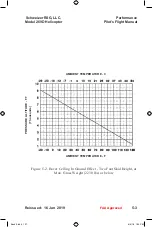
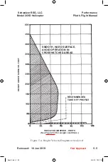
Page 123: ...Height Takeoff Power 91 N2 5 3 5 3 Airspeed Calibration Curve 5 4 5 4 Height Velocity Diagram at Sea Level 5 5 5 5 Gross Weight Limitations for Height Velocity Diagram 5 6 5 6 Density Altitude Chart 5 7 5 7 Power Check Chart External Rolls Royce 250 C20W Engine 5 9 5 8 Power Check Chart Internal Rolls Royce 250 C20W Engine 5 10 Performance Schweizer RSG LLC Model 269D Helicopter Pilot s Flight Man...

Page 124: ...This page is intentionally left blank Performance Pilot s Flight Manual Schweizer RSG LLC Model 269D Helicopter 5 ii Reissued 16 Jan 2019 FAA Approved Book 3 indd 124 8 4 19 1 25 PM ...

Page 125: ...be adequate in winds up to 17 knots Indicated airspeed IAS corrected for position and instrument error equals calibrated airspeed CAS See Fig 5 3 Airspeed Calibration Curve See Fig 5 4 for height velocity diagram at sea level See Fig 5 5 for gross weight limitations for height velocity diagram See Fig 5 6 for density altitude chart Performance data defined in this section is valid for Model 269D H...

Page 126: ...ormance Pilot s Flight Manual Schweizer RSG LLC Model 269D Helicopter 5 2 Reissued 16 Jan 2019 PRESSURE ALTITUDE FT Thousands INDICATED AIRSPEED Knots NOTE SUBTRACT 1 KNOT FOR EACH 10 DEG F ABOVE ISA CONDITIONS FAA Approved Book 3 indd 126 8 4 19 1 25 PM ...

Page 127: ...ight at Max Gross Weight 2230 lbs or below Performance Schweizer RSG LLC Model 269D Helicopter Pilot s Flight Manual 5 3 Reissued 16 Jan 2019 PRESSURE ALTITUDE FT Thousands AMBIENT TEMPERATURE F AMBIENT TEMPERATURE C FAA Approved Book 3 indd 127 8 4 19 1 25 PM ...

Page 128: ...ve Performance Pilot s Flight Manual Schweizer RSG LLC Model 269D Helicopter 5 4 Reissued 16 Jan 2019 NO INSTRUMENT ERROR CALIBRATED AIRSPEED KNOTS INDICATED AIRSPEED KNOTS AIRSPEED CALIBRATION FAA Approved Book 3 indd 128 8 4 19 1 25 PM ...

Page 129: ...l 269D Helicopter Pilot s Flight Manual 5 5 Reissued 16 Jan 2019 INDICATED AIRSPEED KNOTS See Figure 5 5 for weight conditions HEIGHT ABOVE SURFACE FEET SMOOTH HARD SURFACE AVOID OPERATION IN CROSSHATCHED AREAS RECOMMENDED TAKE OFF PROFILE FAA Approved Book 3 indd 129 8 4 19 1 25 PM ...

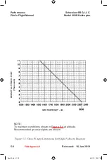
Page 130: ...e Pilot s Flight Manual Schweizer RSG LLC Model 269D Helicopter 5 6 Reissued 16 Jan 2019 NOTE To maintain conditions shown in Figure 5 4 at altitude Recommended gross weights are shown DENSITY ALTITUDE FEET Thousands GROSS WEIGHT LB FAA Approved Book 3 indd 130 8 4 19 1 25 PM ...

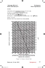
Page 131: ...UDE 15 C OAT 100 IAS FIND DENSITY ALTITUDE FOLLOW 15 C LINE TO 6 000 FT PRESSURE ALTITUDE LINE READ DENSITY ALTITUDE 3780 FT FIND 1 σ SIGMA FACTOR READ DIRECTLY ACROSS FROM DENSITY ALTITUDE 3780 1 058 1 σ SIGMA 100 IAS 98 5 CAS 98 5 CAS X 1 058 104 2 ROUND TO 104 0 TRUE AIRSPEED 1 TEMPERATURE DEGREES F DENSITY ALTITUDE X 1000 FEET FAA Approved Book 3 indd 131 8 4 19 1 25 PM ...

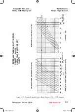
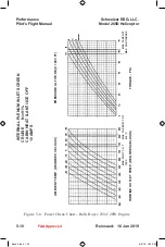
Page 132: ...mation on trend analysis The power check chart is based on the following conditions 91 N2 Cabin heat defrost and engine anti ice OFF Aircraft in cruise attitude 10 amperes electrical load NOTE Operation of alternate air door does not affect this data Use of chart The primary use of the chart is illustrated by the EXAMPLE page 5 11 and by the sample arrows shown on the power check chart To determin...

Page 133: ...Manual 5 9 Reissued 16 Jan 2019 MAX TAKEOFF MAX CONTINUOUS TORQUE PSI PRESSURE ALTITUDE X 1000 FT MAX TAKEOFF T O T 810 C MAX CONT T O T 738 C TURBINE OUTLET TEMP DEGREES CELSIUS AMBIENT TEMP DEGREES CELSIUS EXTERNAL PLENUM INLET SCREEN CRUISE N 2 91 CABIN HEAT ANTI ICE OFF 10 AMPS FAA Approved Book 3 indd 133 8 4 19 1 25 PM ...

Page 134: ...opter 5 10 Reissued 16 Jan 2019 INTERNAL PLENUM INLET SCREEN CRUISE N 2 91 CABIN HEAT ANTI ICE OFF 10 AMPS AMBIENT TEMP DEGREES CELSIUS TURBINE OUTLET TEMP DEGREES CELSIUS MAX CONT T O T 738 C MAX TAKEOFF T O T 810 C PRESSURE ALTITUDE X 1000 FT TORQUE PSI MAX CONTINUOUS MAX TAKEOFF FAA Approved Book 3 indd 134 8 4 19 1 25 PM ...

Page 135: ...pressure from Davtron Indicator NOTE Best power check data is obtained at 61 7 psi torque or 810 C TOT Allow engine to stabilize at least one minute at the test power setting before recording data EXAMPLE WANTED Check engine performance DATA OBTAINED DURING FLIGHT Torque 54 psig TOT 650 C PA 6000 feet OAT 10 C Performance Schweizer RSG LLC Model 269D Helicopter Pilot s Flight Manual 5 11 Reissued ...

Page 136: ...ation TOT If the TOT observed had been higher than the specification TOT read from the chart some power deterioration will have occurred and the performance given in this manual may not be obtained 3 When trend check procedures indicate engine power deterioration re fer to the Rolls Royce Operation and Maintenance Manual for correc tive action 5 3 NOISE At maximum gross weight the helicopter produ...

Page 137: ... 6 3 6 2 Station Diagram 6 5 6 3 Longitudinal Center of Gravity Limits 6 6 6 4 Lateral Center of Gravity Limits 6 7 6 5 Sample Weight and Balance Report 6 9 6 6 Basic Weight and Balance Record 6 11 6 7 Fuel Buttline 6 14 6 8 Specific Weight of Fuels and Lubricants 6 19 List of Tables Table Title Page 6 1 Center of Gravity Limits 6 2 6 2 Weights and Longitudinal Moments Pilot Passenger Baggage 6 16...

Page 138: ...This page is intentionally left blank Weight and Balance Pilot s Flight Manual Schweizer RSG LLC Model 269D Helicopter 6 ii Reissued 16 Jan 2019 Book 3 indd 138 8 4 19 1 25 PM ...

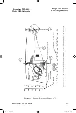
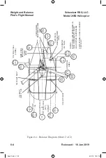
Page 139: ...ted in the crew compartment looking forward See Fig 6 3 for longitudinal center of gravity limits See Fig 6 4 for lateral center of gravity limits Stowage Area Behind Seats Limited to 50 pounds each side Fig 6 1 Center of Gravity Locations Fig 6 1 and 6 2 Longitudinal Sta in Lateral B L in Fuel 104 20 See Fig 6 7 LH Seat 68 60 21 50 Center Seat 78 60 1 25 Right Seat 68 60 23 75 Baggage Compartment...

Page 140: ...st adverse position Table 6 1 Center of Gravity Limits Gross Weight lb Longitudinal C G Limit Lateral C G Limit Sta in B L in Forward Aft Right Left 2230 94 1 96 0 2 4 9 1950 92 8 98 8 3 7 2 2 1750 below 92 0 101 0 4 5 3 0 NOTE Forward C G limit is 94 1 in at 2230 lbs varying linearly to 92 0 in at 1750 lbs and below Aft C G limit is 96 0 in at 2230 lbs varying linearly to 101 0 in at 1750 lbs bel...

Page 141: ...Flight Manual 6 3 Reissued 16 Jan 2019 STA 100 STA 283 5 STA 183 45 STA 101 STA 92 STA 73 HORIZONTAL DATUM LINE CENTER OF GRAVITY LIMITS VERTICAL DATUM LINE WATERLINE CENTER SECTION FRAME STA 15 15 NOTE VERTICAL AND HORIZONTAL DATUM AND WATERLINE SCALES ARE GRADUATED IN INCHES Book 3 indd 141 8 4 19 1 25 PM ...

Page 142: ...04 2 STA 100 0 STA 114 4 STA 125 0 STA 117 0 STA 84 0 STA 78 6 STA 68 6 INBD FACE BAGGAGE COMP REF CG RIGHT SEAT CG SEAT R B L 1 25 CG LEFT SEAT COPILOT C L HELICOPTER C L C G FUEL CELL LAT PILOT C L STOWAGE AREA CG ENGINE OIL TANK FWD FACE BAGGAGE COMP REF CG BAGGAGE CENTERED LOAD REF CG FUEL CELL LONG NOTES BUTTLINES ARE MEASURED IN INCH INCREMENTS FROM HELICOPTER CENTERLINE FOR LATERAL FUEL CG ...

Page 143: ... WL 102 68 CG INSTRUMENT PANEL FACE WL 0 0 WL 44 42 STA 183 45 WL 21 73 WL 17 01 WL 96 75 WL 48 67 STA 104 2 STA 100 0 STA 48 0 STA 114 4 STA 239 88 STA 283 5 STA 117 25 STA 73 0 STA 15 15 CENTER SECTION FRAME FWD JACKING POINT B L 4 0 IN AFT JACKING POINT B L 18 625 IN CG ENGINE OIL TANK CG FUEL CELL Book 3 indd 143 8 4 19 1 25 PM ...

Page 144: ...al Center of Gravity Limits Weight and Balance Pilot s Flight Manual Schweizer RSG LLC Model 269D Helicopter 6 6 Reissued 16 Jan 2019 FUSELAGE STATION INCHES FWD AFT GROSS WEIGHT LBS ROTOR C L Book 3 indd 144 8 4 19 1 25 PM ...

Page 145: ...e Schweizer RSG LLC Model 269D Helicopter Pilot s Flight Manual 6 7 Figure 6 4 Lateral Center of Gravity Limits Reissued 16 Jan 2019 FUSELAGE B L INCHES LEFT RIGHT GROSS WEIGHT LBS AC C L Book 3 indd 145 8 4 19 1 25 PM ...

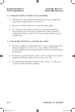
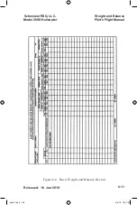
Page 146: ...l 6 3 EQUIPMENT REMOVAL OR INSTALLATION Removal or addition of equipment must be entered on the Repair and Alteration Report Form FAA 337 in accordance with Federal Aviation Regulations which shall then become part of the Helicopter Records file Record the weight and balance effects of these changes in the Weight and Balance Record inserted in this section Fig 6 6 Use the Balance and Station Diagr...

Page 147: ...ACTION 117 25 LONGITUDINAL MOMENT ARM OF NOSE REACTION 73 0 LATERAL MOMENT ARM OF MAIN REACTION 18 625 IN LATERAL MOMENT ARM OF NOSE REACTION 4 0 IN FUEL OIL ABOARD AT TIME OF WEIGHING EMPTY FULL FUEL ENGINE OIL MAIN GEAR BOX TAIL GEAR BOX MISSING EQUIPMENT AT TIME OF WEIGHING ITEM WEIGHT LBS LONG ARM IN LONG MOMENT IN LB LAT ARM IN LAT MOMENT IN LB ELT 3 0 84 0 252 25 75 UNUSABLE FUEL 5 4 104 2 5...

Page 148: ...ADING TOWARDS FORWARD C G WEIGHT LBS LONG ARM IN LONG MOMENT IN LB LAT ARM IN LAT MOMENT IN LB Total Delivery Weight 1148 105 8 121402 69 792 Right Seat 170 68 6 11662 23 75 4038 Center Seat 170 78 6 13362 1 25 213 Left Seat 170 68 6 11662 21 50 3655 Fuel Quantity 100 104 2 10420 17 0 1700 Gross Weight 1758 95 8 168508 1 76 3088 EXAMPLE OF LOADING TOWARDS AFT C G WEIGHT LBS LONG ARM IN LONG MOMENT...

Page 149: ...Figure 6 6 Basic Weight and Balance Record Weight and Balance Schweizer RSG LLC Model 269D Helicopter Pilot s Flight Manual 6 11 Reissued 16 Jan 2019 Book 3 indd 149 8 4 19 1 25 PM ...

Page 150: ...b Long Arm in Long Moment in lb Delivered Weight 1148 105 8 121402 Pilot 170 68 6 11662 Passenger Outboard 170 68 6 11662 Passenger Center 170 78 6 13362 Stowage Area Station 84 0 50 84 0 4200 1 Zero Fuel Weight 1708 95 0 162 288 Add Fuel 390 104 2 40638 2 Gross Weight 2098 96 7 202926 Calculation of Lateral CG CG Zero Fuel Weight Moment at Zero Fuel Weight 162288 95 0 in Zero Fuel Weight 1708 CG ...

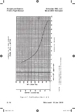
Page 151: ...el gross weight see Example I NOTE Lateral C G must be controlled Refer to Para 6 5 CAUTION Do not exceed 2230 pounds gross weight NOTE Ballast may be carried in the stowage area behind seats or stowed and secured by seat belt and shoulder harness in opposite front seat Ballast may consist of shot sandbags or similar material ade quately contained and secured Weight and Balance Schweizer RSG LLC M...

Page 152: ...ce Pilot s Flight Manual Schweizer RSG LLC Model 269D Helicopter 6 14 Reissued 16 Jan 2019 LATERAL C G VS FUEL WEIGHT FUEL JP 4 JET B LATERAL C G INCHES NOTES 1 ONE GALLON JP 4 6 50 LBS 2 FUEL LONGITUDINAL C G IS 104 2 INCHES Book 3 indd 152 8 4 19 1 25 PM ...

Page 153: ...hweizer RSG LLC Model 269D Helicopter Pilot s Flight Manual 6 15 Reissued 16 Jan 2019 NOTES 1 ONE GALLON JET A JP 5 6 73 LBS 2 FUEL LONGITUDINAL C G IS 104 2 INCHES LATERAL C G INCHES LATERAL C G VS FUEL WEIGHT FUEL JP 5 JET A A 1 Book 3 indd 153 8 4 19 1 25 PM ...

Page 154: ...0 10976 12576 10976 170 11662 13362 11662 180 12348 14148 12348 190 13034 14934 13034 200 13720 15720 13720 220 15092 17292 15092 240 16464 18864 16464 Baggage Weights and Longitudinal Moments Baggage Weight lb Moment in lbs Behind Seat Station 84 0 10 840 20 1680 30 2520 40 3360 50 4200 60 5040 70 5880 80 6720 90 7560 100 8400 Maximum Capacity Each Location Note For all quantities of fuel longitu...

Page 155: ...avity refer to Fig 6 4 and Table 6 1 EXAMPLE II Items Weight lb Lateral Arm in Lateral Moment in lb Delivered Weight 1148 69 792 Pilot 170 23 75 4038 Passenger Outboard 170 21 50 3655 Passenger Center 170 1 25 213 Stowage Area 50 21 50 1075 1 Zero Fuel Weight 1708 18 313 Add Fuel 390 4 4 1716 2 Gross Weight 2098 96 2029 z z Calculation of Lateral CG z z z CG Zero Fuel Weight Moment at Zero Fuel We...

Page 156: ...08 pounds and 96 inch at 2098 pounds fall within the lateral limits CAUTION Gross weight must not exceed 2230 lbs Weight and Balance Schweizer RSG LLC Model 269D Helicopter Pilot s Flight Manual 6 18 Reissued 16 Jan 2019 Book 3 indd 156 8 4 19 1 25 PM ...

Page 157: ...cific Weight of Fuels and Lubricants Weight and Balance Schweizer RSG LLC Model 269D Helicopter Pilot s Flight Manual 6 19 Reissued 16 Jan 2019 SPECIFIC WEIGHT LB U S GAL TEMPERATURE F Book 3 indd 157 8 4 19 1 25 PM ...

Page 158: ...This page is left blank intentionally Weight and Balance Pilot s Flight Manual Schweizer RSG LLC Model 269D Helicopter 6 20 Reissued 16 Jan 2019 Book 3 indd 158 8 4 19 1 25 PM ...

Page 159: ...7 12 Collective Stick Installation and Removal 7 19 7 13 Moving and Towing Helicopter 7 20 7 14 Parking 7 21 7 15 Mooring 7 22 7 16 Servicing 7 23 7 17 Filling Fuel System 7 29 7 18 Defueling Fuel System 7 30 7 19 Draining Engine Oil System 7 30 7 20 Filling Engine Oil System 7 30 7 21 Draining Main Transmission 7 31 7 22 Filling Main Transmission 7 31 7 23 Draining Tail Rotor Transmission 7 32 7 ...

Page 160: ...ng Engine Oil Filters 7 38 7 33 Cleaning Engine Compressor 7 38 7 34 Cleaning Plenum Chamber Screen 7 38 7 35 Fluid Leak Analysis 7 38 7 36 Engine Oil Leaks 7 39 7 37 Landing Gear Damper Hydraulic Fluid Leak 7 39 7 38 Overrunning Clutch Oil Leakage 7 39 7 39 Preservation and Storage 7 40 7 40 Flyable Storage No Time Limit 7 40 7 41 Torque Data 7 41 7 42 Hourmeter Installation 7 41 7 43 Ground Hand...

Page 161: ...ions 7 14 7 3 Jacking and Leveling 7 18 7 4 Parking and Mooring 7 21 7 5 Servicing Points 7 26 7 6 Access and Inspection Provisions and Locations 7 35 Handling Servicing Maint Schweizer RSG LLC Model 269D Helicopter Pilot s Flight Manual 7 iii Reissued 16 Jan 2019 Book 3 indd 161 8 4 19 1 25 PM ...

Page 162: ...This page is intentionally left blank Handling Servicing Maint Pilot s Flight Manual Schweizer RSG LLC Model 269D Helicopter 7 iv Reissued 16 Jan 2019 Book 3 indd 162 8 4 19 1 25 PM ...

Page 163: ...ected parts are to be inspected for discrepancies and an operational check is to be performed CAUTIONS and WARNINGS Caution and warning statements throughout the HMI and this manual are provided to promote safe maintenance of the heli copter General Information Inspections All inspections include visual inspection of the specified system equipment or component for cracks corrosion distortion secu ...

Page 164: ...ions are grouped by location so that they can be per formed on an area by area basis Thus inspection of the entire helicopter may be accomplished by starting at the front and working in clockwise progression to completion The following inspections may be performed by a helicopter qualified pilot or mechanic WHAT TO INSPECT POWER OFF FRONT CANOPY AND PILOT S COMPARTMENT Canopy and front exterior fo...

Page 165: ...al quick release locking pins for condition and security Check for minimum cyclic friction adjustment resistance to turning of spring with fingers NOTE With main rotor blades stationary some friction drag is felt in the cyclic The collective also has some drag plus resistance of the collective bungee spring Collective stick s and cyclic stick s for condition secure closure and free movement throug...

Page 166: ...rom damage No evidence of oil leakage around fuselage drain hole Engine exhaust duct secure free from cracks or distortion Scavenge oil filter for extended bypass indicator Right hand static port free of obstruction Access inspection and compartment panels covers for secure closure AFT FUSELAGE CAUTION The following special check applies to 269D3300 1 Aft Fuselage Assemblies only S N 63 subsequent...

Page 167: ...otor transmission for security of mounting Check torque stripes for movement of the transmission cracks in the torque paint fretting and gaps between the faying surfaces and or rotation of nuts and studs Tail rotor transmission for excessive oil leakage and correct oil level replenish if low Tail rotor blade abrasion strips free of damage no excessive erosion noted No separation in bond around edg...

Page 168: ...dial molded ridges on each bearing face as teetering takes place Discontinuity in molded ridges indicates bearing failure NOTE Light swelling pock marks and crumbs are surface conditions and do not indicate bearing failure ENGINE COMPARTMENT Rear cross beams for yielding evidence of hard landing Fuel cell for leakage and security Drain fuel sample from fuel cell sump drain valve into suitable cont...

Page 169: ...1 and N2 control linkage for free operation full travel security and obvious damage Pilot s and copilot s throttle rigging checks at FULL OPEN GROUND IDLE and CUTOFF positions Fuel controls and compressor exterior for condition and security Firewall insulator panels for security and obvious damage Engine wiring harness leads for burning chafing cracking connectors for looseness and broken or missi...

Page 170: ... and free from damage Upper canopy clean and free from damage Pylon clean and free from damage Main rotor hub pitch housing and swashplate for obvious damage Blade pitch links lockwire for security Visually inspect main rotor blade damper attach fitting for cracks wear and corrosion Damper for obvious damage and for security Scissors for any evidence of damage or deformation of crank or link All m...

Page 171: ...urce during POWER ON inspection not battery Push PRESS TO TEST switch All caution and warning lights ON adjust instrument light rheostat knob verify CAUTION lights dim Check ENGINE OUT audio by manually positioning GEN switch to ON Operate pilot s and copilot s cyclic trim switch briefly in all four directions Check for trim motor operation noise Operate pilot s and copilot s N2 beep switch up and...

Page 172: ...r check Communication navigation and intercom equipment for proper operation turn switches OFF after check All installed auxiliary or optional systems and equipment for proper function 7 2 RELATED PUBLICATIONS Refer to Basic HMI Section 2 for a listing of related publications and directives 7 3 MAINTENANCE INFORMATION REQUESTS Questions that may arise during maintenance of the helicopter or it s c...

Page 173: ... furnished visual inspection for integrity damage and serviceability applies for these items components and equipment 7 5 MALFUNCTION INFORMATION REPORT This form may be used to report to Schweizer RSG in detail any service difficulties encountered with any Schweizer helicopter Use of this form is encouraged and recommended to enable Schweizer RSG to provide owners and operators with improved serv...

Page 174: ...on and waterline throughout this manual To assist in locating the components being discussed refer to the station diagram in Section VI The maximum weights for large components that may require hoisting are listed in Table 7 1 Handling Servicing Maint Pilot s Flight Manual Schweizer RSG LLC Model 269D Helicopter 7 12 Reissued 16 Jan 2019 Book 3 indd 174 8 4 19 1 25 PM ...

Page 175: ...19 7 13 VERTICAL STABILIZER TAIL ROTOR TRANSMISSION TAIL ROTOR AFT FUSELAGE HORIZONTAL STABILIZER TAIL ROTOR DRIVE SHAFT BELT DRIVE TRANSMISSION CENTER SECTION FRAME ENGINE LANDING GEAR DOOR CANOPY MAIN ROTOR DRIVE SHAFT MAIN ROTOR BLADE MAIN ROTOR HUB MAIN ROTOR CONTROL ROD FUEL CELL MAIN TRANSMISSION Book 3 indd 175 8 4 19 1 25 PM ...

Page 176: ...or blade aft 30 ft 11 in Weights Design Gross Weight 2 230 lbs External Load Gross Weight 2 230 lbs Empty Weight approximate 1 100 lbs Useful Load approximate 1 130 lbs Powerplant Make Rolls Royce Type Gas Turbine Designation 250 C20W Power Rating 220 HP 235 HP 5 MIN LIMIT Std Capacity Fuel 60 8 U S Gal Useable Fuel Capacity 60 0 U S Gal Generator Capacity 150 Amps 67 77 102 68 60 72 19 62 66 16 7...

Page 177: ...odel 269D Helicopter Pilot s Flight Manual 7 15 Reissued 16 Jan 2019 269A1185 1 main rotor blade 23 75 trailing edge tab 269A1185 5 main rotor blade 74 25 trailing edge tab shown 74 25 17 00 161 08 2 80 50 51 00 96 75 48 67 17 01 W L 0 00 268 50 43 00 58 00 10 Book 3 indd 177 8 4 19 1 25 PM ...

Page 178: ...owing paragraphs present instructions and precautions for all ground handling functions 7 8 USE OF EXTERNAL POWER The external receptacle is located on the lower right side L H side optional of the helicopter Any source of external 28 volt direct current power with sufficient amperage rating may be used Engine starting requirements are approximately 375 amperes Before connecting external power be ...

Page 179: ...are perpendicular at all times When helicopter is jacked from one end only use blocking under skids as necessary to maintain stability NOTE A recessed pad is required to mate with the jacking lugs Place suitable jacks under forward jacking lug and aft jacking pads Raise helicopter to desired height Handling Servicing Maint Schweizer RSG LLC Model 269D Helicopter Pilot s Flight Manual 7 17 Reissued...

Page 180: ...ING PAD LH AFT JACKING PAD RH JACKING POINT Figure 7 3 Jacking and Leveling Handling Servicing Maint Pilot s Flight Manual Schweizer RSG LLC Model 269D Helicopter 7 18 Reissued 16 Jan 2019 DETAIL A A Book 3 indd 180 8 4 19 1 25 PM ...

Page 181: ...an From inside surface insert plumb bob cord thru hole provided in R H canopy frame Adjust cord length to position plumb bob approximately 1 8 inch above target Using jacks adjust height of helicopter along the longitudinal and or lateral axis until the plumb bob is aligned with the center of target 7 12 COLLECTIVE STICK INSTALLATION AND REMOVAL To install collective stick set the N1 control lever...

Page 182: ...i tion Remove the handle Do not operate the helicopter with the wheels in stalled in the ground handling position CAUTION When balancing moving the helicopter by hand do not push on stabilizers or any other component or surface that may sustain damage from ground handling or pushing Move helicopter on ground by manually balancing on ground handling wheels and pushing on tail rotor transmission hou...

Page 183: ...sition where there is adequate blade clear ance from nearby objects on most level ground available Figure 7 4 Parking and Mooring Handling Servicing Maint Schweizer RSG LLC Model 269D Helicopter 7 14 PARKING Fig 7 4 Pilot s Flight Manual 7 21 Reissued 16 Jan 2019 MAIN ROTOR BLADE TIEDOWN SLEEVE AFT FUSELAGE TIE OFF POINT EXHAUST STARTER COOLING PLUG COVER MAST PLUG COVER PLENUM CHAMBER COVER AFT T...

Page 184: ... gear step For longer duration parking also perform the following steps Install cover on plenum chamber screen exhaust vent ex haust starter cooling plug mast plug step plug pitot tube 7 15 MOORING Whenever severe storm conditions or wind velocities higher than 50 knots are forecast helicopter should be housed in hanger or evacuated to a safer area If these precautions are not possible moor helico...

Page 185: ...el skins attach lines to forward stakes mooring an chors 7 16 SERVICING Servicing of helicopter includes replenishment of fuel changing or replenishment of oil and other such maintenance functions Fuels oils and other servicing materials and capacities are listed in Table 7 2 CAUTION Use extreme care when applying any type of lubrication grease oil dry film etc in vicinity of teflon bearings Most ...

Page 186: ...ed lubricants must conform to the specification indicated 2 At 4 4 C 40 F and below fuel must contain anti icing additive MIL I 27686 For blending information and authorized fuels refer to Rolls Royce Operation and Maintenance Manuals 3 MIL L 22851 Oil Grade 10 or 20 or Oil SAE 10 or 20 approved for use at 17 8 C 0 F and above in overrunning clutch 4 SAE HD90 approved for use at 17 8 C 0 F to 43 3...

Page 187: ...lly approved by the manufacturer If type of grease is to be changed bearing must be thor oughly cleaned of all grease not purged Purging is acceptable only when relubricating with same type of grease 7 For Model 250 Series engine oil data refer to Rolls Royce Operation and Maintenance Manual Handling Servicing Maint Schweizer RSG LLC Model 269D Helicopter Pilot s Flight Manual 7 25 Reissued 16 Jan...

Page 188: ...g Maint Pilot s Flight Manual Schweizer RSG LLC Model 269D Helicopter 7 26 Reissued 16 Jan 2019 FUEL CELL FILLER CAP DETAIL A DETAIL C DETAIL B FILLER PORT CAP ENGINE OIL TANK SIGHT GAUGE SUMP DRAIN VALVE SUMP DRAIN TUBE DETAIL A Book 3 indd 188 8 4 19 1 25 PM ...

Page 189: ...eizer RSG LLC Model 269D Helicopter Pilot s Flight Manual 7 27 Reissued 16 Jan 2019 ENGINE TRANSMISSION OIL COOLER DRAIN VALVE DRAIN TUBE FUEL CELL SHUT OFF VALVE ENGINE SHUT OFF VALVE OVERBOARD DRAIN TUBE SUMP DRAIN VALVE DETAIL C DETAIL B Book 3 indd 189 8 4 19 1 25 PM ...

Page 190: ...efore starting fueling or defueling operation the following sequence should be observed Connect a grounding cable from the fueling vehicle to a satisfactory ground Connect a ground cable from ground to the aircraft Do not attach ground cables to the radio antenna Connect a grounding cable from the fueling vehicle to the helicop ter The fueling vehicle may be equipped with a T or Y cable permitting...

Page 191: ...r in level attitude to achieve accurate quantities Maintain constant visual check to prevent overfilling and spillage Hold fuel filler nozzle firmly while inserted in fuel tank filler neck Never block the nozzle lever in the open position Be sure fuel filler cap is replaced and securely latched when fueling is completed Energizing of radio and electrical equipment in the helicopter while dispensin...

Page 192: ...edge of indicator represents 55 U S gallons Note Use care not to damage or scrape indicator during fueling operations 7 18 DEFUELING FUEL SYSTEM Defueling operation should be accomplished with helicopter as level as possible and grounded to all equipment in contact with fuel Fuel system may be defueled in two ways Defuel through filler port using a pump Defuel by holding the sump drain valve open ...

Page 193: ...lve Allow sufficient time for oil to drain from sump If damaged replace O rings used with magnetic drain chip detector and valve Reinstall magnetic drain chip detector and self closing valve in oil sump lockwire in place 7 22 FILLING MAIN TRANSMISSION Access is thru R H main access door Transmission gearbox oil should be replenished when low Depress button and withdraw dipstick from transmission V...

Page 194: ...n low Visually check oil level in sight indicator Oil level should be above ADD mark Cut lockwire and remove filler plug in top of sight gauge extension With aircraft at a level attitude add oil through access hole at top of sight gauge extension until oil level reaches the shoulder in the ac cess hole of the sight gauge extension Reinstall tighten and lockwire plug in sight gauge extension 7 25 R...

Page 195: ...e covers over engine inlet screens Covers should not be removed until work is complete and debris is thoroughly cleaned out of the area Removable hinged access doors and panels are provided in the helicopter for servicing inspection removal installation and adjustment of components Locations of access and inspection provisions are shown in Fig 7 6 Areas components and items accessible through the ...

Page 196: ... door LH Electrical components wiring belt drive transmission main transmis sion battery fuel lines oil lines en gine oil tank sight gauge Main access door RH Belt drive transmission main trans mission dipstick fuel lines oil lines flight controls generator control unit oil filter Aft access door Wiring battery cable battery relay optional location internal plenum inlet screen Aft access panel Tai...

Page 197: ...PANEL LH FORWARD ACCESS PANEL TOWER ASSEMBLY PANEL LH PLENUM CHAMBER SCREEN STAB ACCESS PANEL MAIN ACCESS DOOR LH ENGINE ACCESS PANEL LH LOWER ENGINE ACCESS PANEL COLLECTIVE STICK ACCESS PANEL LH PITOT TUBE TOWER ASSEMBLY PANEL RH INSTRUMENT CONSOLE SIDE PANEL LH ENGINE ACCESS PANEL RH MAIN ACCESS DOOR RH AFT ACCESS DOOR AFT ACCESS PANEL EXTERNAL POWER RECEPTACLE Book 3 indd 197 8 4 19 1 25 PM ...

Page 198: ...ions from floor and other metal surfaces with vacuum cleaner or small hand brush Sponge soiled upholstery and trim panels with a mild soap and warm water solution Avoid complete soaking of upholstery and trim panels Wipe solution residue from upholstery with cloth dampened with clean water Remove imbedded grease or dirt from upholstery and carpeting by sponging or wiping with an upholstery cleanin...

Page 199: ... and dry with soft cloth 7 31 CLEANING TRANSPARENT PLASTIC CAUTION Never attempt to dry plastic panels with cloth To do so causes any abrasive particles lying on plastic to scratch or dull surface Wiping with dry cloth also builds up an electrostatic charge that attracts dust particles from air Clean outside surfaces of plastic panels by rinsing with clean water and rubbing lightly with palm of ha...

Page 200: ...ak approximately 15 minutes Flush out with clean water Allow screen to drain and air dry thoroughly Install plenum chamber screen 7 35 FLUID LEAK ANALYSIS Main or Tail Rotor Transmission Oil Leak Oil leakage seepage or capillary wetting at oil seals or assembly joint lines of main or tail rotor transmission is permissible if leakage rate does not exceed two cc per hour one drop per minute An accep...

Page 201: ...so have slight oil seepage from oil trapped in end cap threads during assembly Neither of these should be considered damper leakage or cause for damper replacement Hydraulic fluid leakage from any landing gear damper is not permissible If leakage is present damper assembly should be removed and serviceable unit installed If leaking landing gear damper is not replaced when leakage is noticed contin...

Page 202: ... Daily Inspection Ensure that fuel cell is full topped off and that oil in engine oil tank and main and tail rotor transmissions is at full level Ensure that fuel shutoff valve is closed NOTE Avoid closing valve after engine shutdown until engine compartment has cooled to near ambient temperature Storage To maintain flyable storage condition perform daily inspection ground runup must be performed ...

Page 203: ...cockpit door positioning air vents openings downward Install covers and equipment used to park and moor helicopter Install static ground Avoid engine N2 steady state operation 71 to 88 Operation within the speed avoidance range is permitted for the preflight checks specified in this flight manual Transient operation through the speed range is to be accomplished as expediently as possible NOTE Tran...

Page 204: ...Handling Servicing Maint Pilot s Flight Manual Schweizer RSG LLC Model 269D Helicopter 7 40B Reissued 16 Jan 2019 This page is intentionally left blank Book 3 indd 204 8 4 19 1 25 PM ...

Page 205: ...main rotor transmission oil pressure is above the minimum value main rotor turning warning light out When this installation is utilized no multiplying factor is required when the re corded time is used to determine periodic inspection requirements overhaul intervals and the service life of life limited components In the optional landing gear actuated hourmeter installation the hourmeter is actuate...

Page 206: ... flight hours used Flight hours recorded by the pilot should be used to confirm the accuracy of the hourmeter s read ing 7 43 GROUND HANDLING WHEELS Two configurations of ground handling wheels are available for the helicopter standard special tool design and single wheel stowed above landing gear skid tubes Standard Special Tool Design These wheel assemblies are configured with long handles which...

Page 207: ...n with retainer clip Be fore Flight in reverse order of lowering the wheels rotate wheel assem blies to the up position and secure in place with lynch pins Do Not Operate the helicopter with the ground handling wheels rotated down into the ground handling position Stow handle in mount and secure with quick release pin Remove the ground handling wheel assemblies from the helicopter by re moving lyn...

Page 208: ...anding gear components may occur if heels catch on a rough surface or the wheels drop into a deep depression Move helicopter on ground by manually balancing on ground handling wheels and pushing on tail rotor transmission housing and any other sturdy structural members of helicopter i e access doors may be opened and assistant may push on adjacent frames and solid structures Handling Servicing Mai...

Page 209: ...age 8 1 Cruise Charts at Standard Sea Level Conditions 91 N2 8 2 8 2 Cruise Charts at 3000 FT Standard Day Conditions 91 N2 8 3 8 3 Cruise Charts at 6000 FT Standard Day Conditions 91 N2 8 4 Operations Performance Schweizer RSG LLC Model 269D Helicopter Pilot s Flight Manual 8 i Reissued 16 Jan 2019 Book 3 indd 209 8 4 19 1 25 PM ...

Page 210: ...This page is left blank intentionally Operations Performance Pilot s Flight Manual Schweizer RSG LLC Model 269D Helicopter 8 ii Reissued 16 Jan 2019 Book 3 indd 210 8 4 19 1 25 PM ...

Page 211: ...ities By use of the data in this section the pilot may obtain maximum utilization of the helicopter Performance data defined in this section is valid for Model 269D Helicopter equipped with either 269A1185 1 or 269A1185 5 main rotor blades Operations Performance Schweizer RSG LLC Model 269D Helicopter Pilot s Flight Manual 8 1 Reissued 16 Jan 2019 Book 3 indd 211 8 4 19 1 25 PM ...

Page 212: ... Conditions 91 N2 Operations Performance Pilot s Flight Manual Schweizer RSG LLC Model 269D Helicopter 8 2 Reissued 16 Jan 2019 SPECIFIC RANGE NM GAL TRUE AIRSPEED KNOTS ENGINE TORQUE PSI TRUE AIRSPEED KNOTS Data Based On Alternate Air Door OPENED or CLOSED Engine Anti Ice OFF Cabin Defrost and Heat OFF Book 3 indd 212 8 4 19 1 25 PM ...

Page 213: ...Conditions 91 N2 Operations Performance Schweizer RSG LLC Model 269D Helicopter Pilot s Flight Manual 8 3 Reissued 16 Jan 2019 SPECIFIC RANGE NM GAL TRUE AIRSPEED KNOTS ENGINE TORQUE PSI TRUE AIRSPEED KNOTS Data Based On Alternate Air Door OPENED or CLOSED Engine Anti Ice OFF Cabin Defrost and Heat OFF Book 3 indd 213 8 4 19 1 25 PM ...

Page 214: ...Conditions 91 N2 Operations Performance Pilot s Flight Manual Schweizer RSG LLC Model 269D Helicopter 8 4 Reissued 16 Jan 2019 SPECIFIC RANGE NM GAL TRUE AIRSPEED KNOTS ENGINE TORQUE PSI TRUE AIRSPEED KNOTS Data Based On Alternate Air Door OPENED or CLOSED Engine Anti Ice OFF Cabin Defrost and Heat OFF Book 3 indd 214 8 4 19 1 25 PM ...

Page 215: ...lity Combined Optional Equipment 9 1 9 4 Listing Optional Equipment Flight Manuals 9 2 9 5 Abbreviations 9 4 List of Tables Table Title Page 9 1 Owner s Manual Supplement 269D Helicopter 9 3 Optional Equipment Schweizer RSG LLC Model 269D Helicopter Pilot s Flight Manual 9 i Reissued 16 Jan 2019 Book 3 indd 215 8 4 19 1 25 PM ...

Page 216: ...This page is intentionally left blank Optional Equipment Pilot s Flight Manual Schweizer RSG LLC Model 269D Helicopter 9 ii Reissued 16 Jan 2019 Book 3 indd 216 8 4 19 1 25 PM ...

Page 217: ... content and usage of Optional Equipment Flight Manual Supplements 9 2 LISTING OPTIONAL EQUIPMENT Table 9 1 lists optional equipment kits and their associated flight manual supplements affecting FAA approved data that appears in Sections II through V of the basic Rotorcraft Flight Manual These kits and other optional equipment not affecting Section V of the basic Rotorcraft Flight Manual are appro...

Page 218: ...s Section III Normal Procedures Section IV and Performance Data Section V The Flight Manual Supplement Data is to be used in conjunction with the basic Rotorcraft Flight Manual data and takes precedence over that data when the equipment is installed Flight operation of the aircraft with optional equipment installed is prohibited if the applicable Flight Manual Supplement is not on board the aircra...

Page 219: ... 5 Search Light Issued 15 Mar 1996 Revised 09 Jul 2002 CSP D 1N Extended Height Landing Gear 269D7100 26 Sep 2008 CSP D 1P Increased Diameter Main Rotor System 269A1002 11 14 Mar 1997 CSP D 1Q Increased Diameter Main Rotor System 269A1002 11 in conjunction with Ex tended Height Landing Gear 269D7100 Issued 14 Mar 1997 Revised 25 Nov 1998 CSP D 1R Thermal Imaging System FLIR Systems Ultra 3000 269D...

Page 220: ... Communication ICS Intercommunication system ind Indicator Nav Navigation rcvr Receiver std Standard VHF Very high frequency xcvr Transceiver Optional Equipment Pilot s Flight Manual Schweizer RSG LLC Model 269D Helicopter 9 4 Reissued 16 Jan 2019 Book 3 indd 220 8 4 19 1 25 PM ...

Reviews: