21
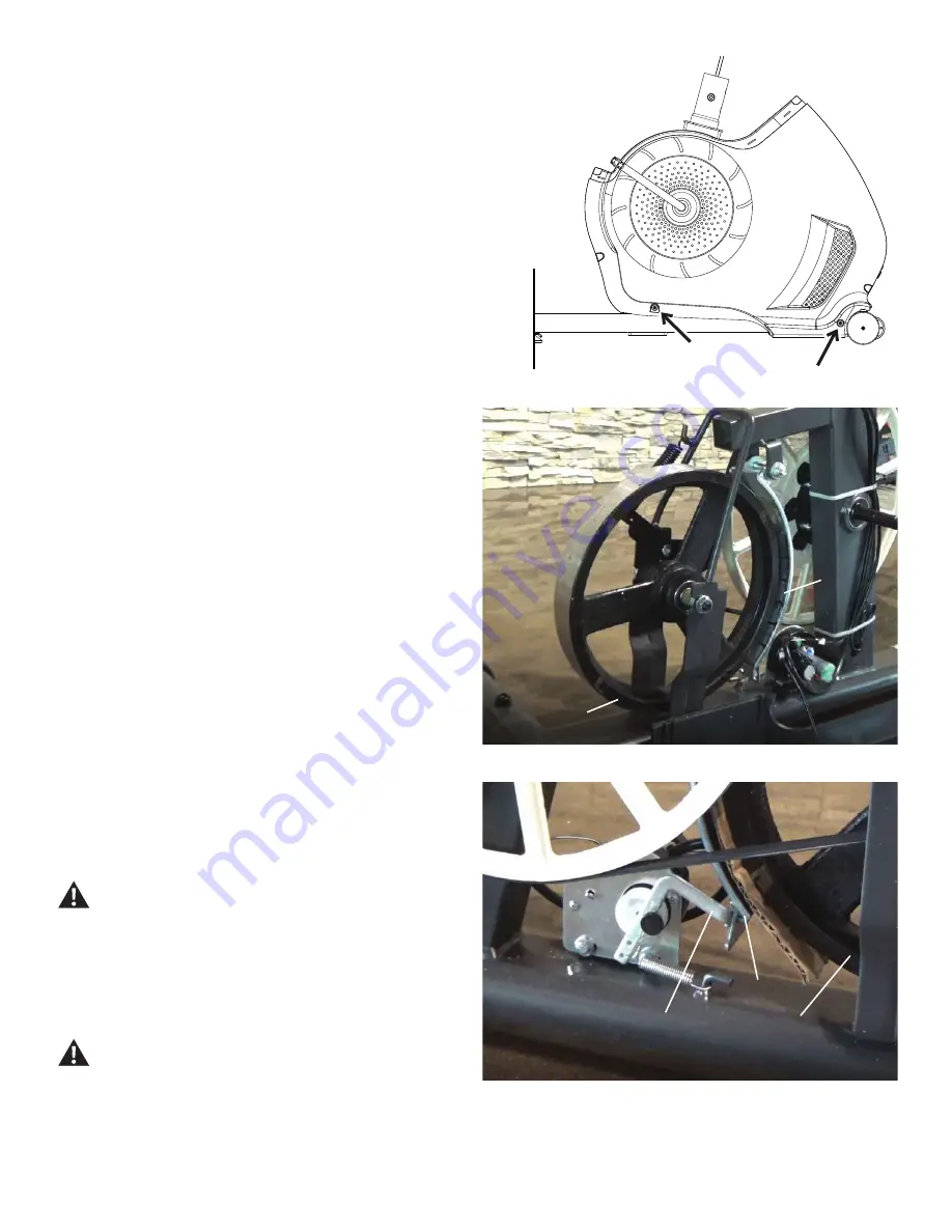
Left side
Right side
B
C
C
B
C1
7.
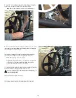
Insert 2.5” x 10” cardboard between the Brake Magnet (C) and the
Flywheel (B), and tape the cardboard to the Brake Magnet.
Note:
Be sure the cardboard covers all of the Brake Magnet.
8.
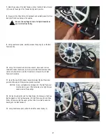
Turn the power on again.
Machine is on. Current is active. There is risk of electrical
shock.
9.
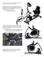
Use the console to set the resistance to the highest level. This moves
the Brake Magnet Arm (C1) forward. After the Brake Magnet Arm stops at
the highest resistance level, turn power off.
Disconnect all power and allow to sit for 5 minutes.
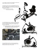
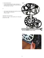
6.
Using a #2 Phillips Screwdriver, remove the 2 screws that secure
the Right Main Shroud. Slowly remove the Right Main Shroud. Set the
hardware and Shroud safely aside for reassembly.


