background image

Summary of Contents for Active series 20 series

Page 1: ...20 SERIES RECUMBENT BIKE ASSEMBLY GUIDE PN 001 7054 REVA 06 14 2007 ASSEMBLY GUIDE ...

Page 2: ...Table of Contents Exploded View 2 Parts List 3 Hardware 4 Assembly Instructions 5 AC Adapter Specifications 15 C_ Z 2 ...

Page 3: ... m x m m ...

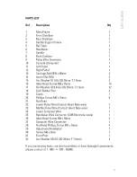
Page 4: ...ad Screw M8 x 15ram FlatWasher ID8 4ram OD25ram T 1 5ram Limit Rubber Pad Crank Phillips Screw M6 x 15ram Not Used Lower PulseWire Contact Heart Ratewire Middle Pulse Wire Contact Heart Ratewire Lower ComputerWire Handlebar Wire Connector CHRElectrode cable Allen Head Screw M8 x 10ram Computer Wire Connector Flat Head Phillips Screw M5 x 10ram Adjustment Handlebar Screw M6 x 8ram Front Post Arc Wa...

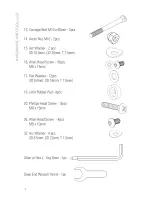
Page 5: ...0 Bmm OD2Bmm T 1 Bmm 16 Allen HeadScrew 16pcs M8 x 1Bmm 17 FlatWasher 12pcs ID 8 4mm OD16mm T 1 Bmm 18 Limit RubberPad 4pcs 20 Phillips HeadScrew 8pcs M8 x 1Bmm 26 Allen HeadScrew 4pcs M8 x 10mm 32 Arc Washer 4 pcs ID 8 Bmm OD22mm T 1 Bmm Allen or HexL Key6mm 1pc Open EndWrench 1Bmm 1pc J ...

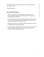
Page 6: ...ime and effort 1 To make the assembly process go faster gather the pieces you need for each step and thoroughly read the assembly instructions for that step prior to starting assembly for the step 2 When attaching two pieces gently lift and look through the bolt holes to help guide the bolt through the holes 3 As a general rule and for all bolts and nuts turn bolts or nuts toward the right to tigh...

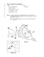
Page 7: ...13 ArcWasher 2 15 Acorn Nut 2 14 Tools Wrench Step 1 Install FrontStabilizer 2 to Main Frame 1 using two Car riage Bolts 13 two ArcWashers 15 and two Acorn Nuts 14 as indicated Figure 1 Note Position FrontStabilizer so arrow ondecal is pointing upwards Figure1A Figure 1 UP_ Sticker Figure 1A ...

Page 8: ...Parts Saddle Support Frame 4 RaiITube 5 Step 2 1 Side Saddle Support Frame 4 onto RaiITube 5 as shown in Figure 2 The wires from the RaiITube pass through the Saddle Support Frame Note Take care not to cut or pinch the wires Figure 2 ...

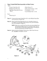
Page 9: ...own in Figure 3A Step 3 2 Side the RailTube Assembly 5 onto the Main Frame 1 and attach using 6 Allen Head Screws 16 and 6 FlatWash ers 17 as shown in Figure 3 NOTE Make sure to push Lower PulseWire 22 andthe Middle Pulse Wire 23 into the Main Frame 1 connection bracket Ensure the wires will not be pinched or severed when assemblingthe RailTubeAssembly 5 to the Main Frame 1 Step 3 3 Attach the 2Li...

Page 10: ...it Rubber Pads 2 18 Step 4 1 Attach the Rear Stabilizer Bar 3 to the RaiITube 5 using 4Allen Head Screws 16 2 FlatWashers 17 and 2 Limiting Rubber Pads 18 DO NOT overtighten the screws attaching the 2 Limiting Rubber Pads 18 NOTE Make sure the RearStabilizer Bar 3 is orientated as illustrated with the bendin the barfacing forward c c Figure 4 ...

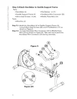
Page 11: ...her 4 17 HandlebarWire Connector 25 Middle PulseWire 23 Step 5 1 Attach the Handlebar 6 to Saddle Support Frame 4 using 4Allen Head Screws 26 and 4 FlatWashers 17 as shown in Figure 5 Step 5 2 Connect HandlebarWire Connector 25 to Middle Pulse Wire 23 as shown in Figure 5A Take care not to pinch the HandlebarWire Connector 25 during assembly ...

Page 12: ...d Back Cushion 8 onto the Saddle Support Frame 4 using 8 Phillips Screws 20 Insert the Phillips Screws through the screw holes in the Saddle Support Frame first when attaching the Saddle and Back Cushion Note There aretwo groups of mountingholes on the Back Cushion 8 so that you may adjustthe height of the backsupport to your preference Figure 6 ...

Page 13: ...ugh the Front Post 31 Step 7 2 Install the Front Post 31 onto the Main Frame 1 using 4 Allen Head Screws 16 and 4ArcWashers 32 Step 7 3 ConnectLower PulseWire 22 to the PulseWire Connector 9 and the Lower ComputerWire 24 to the ComputerWire Connector 27 Note Pushthe wires gently into the Front Post Takecare not to cut or pinch the wires Step 7 4 install the Console 10 to Front Post 31 using 4 Flat...

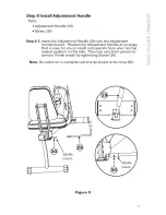
Page 14: ...justment handle mount Position the Adjustment Handle at an angle that is easy for you to reach and operate from your normal seated position on the bike This may vary from person to person Finish install by tightening Screw 30 Note Be careful not to overtighten and strip the threads on the screw 30 Handle mount Figure 8 13 ...

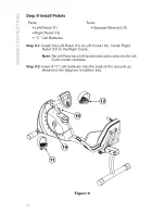
Page 15: ... Step 9 1 Install the Left Pedal 11 to Left Crank 19 Install Right Pedal 12 to the Right Crank Note The Left Pedalhas a left handedtread andscrews into the Left Crankcounter clockwise Step 9 2 Insert 4 C cell batteries into the back of the console as shown by the diagram in battery bay Figure 9 14 ...

Page 16: ...tained from many electronic stores The AC adapter specifications are INPUT A0 120v60Hz 5 7W OUTPUT DO6V 500mA DC PLUG Outer Diameter 5 5_ 0 1 internal Diameter 2 1 _ 0 1 Length 10 0 1 DOWire Length 71in 180cm Wire Diameter 24AWG The DCConnectorJack configuration Outside Negative inside Positive AC ADAPTOR CLASS 2 TRANSFORMER INPUT 120VAC 60Hz 5 7W OUTPUT 6VDC 500mA XXXXX _ XXXXXXXX XXX SAC XXXXXX ...

Page 17: ...rs are tight and components are properly assembled Review all warnings affixed to machine Congralulations Assemblyis complele Please reference the Owner s Manual for information regarding Computer Operation Product Maintenance Warranty Information General Fitness and Exercise Guidelines 1G ...

Page 18: ...e Nautiluslogo Nautilusand Active are either r g ster dtradomarks or tradomatks of NautiltJs hlc Schwhln alld the Schwinn QualityS_al an _g ste_d tradomarks Nautilus _nc Wurld_eadq uarters _ 0 SENautilus D_ Val _ot_ve_ WA _68S Printed in China ...

Reviews: