


20
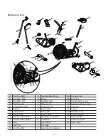
Replace the Crank Belt on the
AD6 Airdyne
®
Upright Bike
Skill Level: II
8001812.010117.B
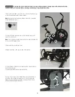
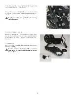
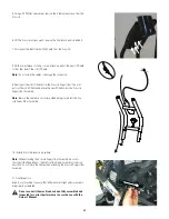
Replacement Procedure
NOTICE:
This document provides instructions for the replacement of the Crank Belt on the Schwinn
®
AD6 Airdyne
®
Upright Bike.
If you need assistance, please call
Schwinn
Customer Service at 1-800-605-3369.
This icon means a potentially hazardous situation which, if not avoided, could result in death or serious injury. Read and
understand all Warnings on this machine.
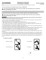
Important Safety Instructions - Before servicing or using this equipment, obey the following warnings:
This icon means a potentially hazardous situation which, if not avoided, could result in death or serious injury. Read and
understand all Warnings on this machine.
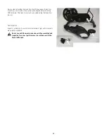
To reduce the risk of electrical shock or usage of the equipment, always remove the batteries from the machine and
wait 5 minutes before cleaning, maintaining or repairing the machine.
• Read and understand the Part Replacement Procedure before working on the machine. Failure to obey the instructions and safety warn-
ings could cause injury to the service technician or bystanders.
• Keep bystanders and children away from the product being serviced at all times.
• Make sure that the repair is done in an appropriate work space away from foot traffic and exposure to bystanders.
• Some components of the equipment can be heavy or awkward. Enlist the service of a second person when you do maintenance steps
involving these components. Do not try to do heavy or awkward steps on your own.
• Use only replacement parts and hardware that are supplied or approved by Nautilus. Failure to use Nautilus-approved replacement parts
can adversely affect the safety and functionality of the equipment creating a risk to users.
• Be sure that all warning stickers and instructional placards applied to the product stay present and in good condition when doing mainte-
nance or replacing components. If necessary request replacement warning stickers or placards from Nautilus customer service.
• Do not try to change the design or functionality of the machine being serviced as this can adversely affect user safety.
• Do not use the machine until all shrouds, instructions, warning labels and correct functionality have been verified and tested for correct
performance.
• This product contains magnets. Magnetic fields can interfere with the normal use of certain medical devices at a close range. Users may
come into proximity of the magnets in the assembly, maintenance, and/or use of the product. Given the obvious importance of these de-
vices, such as a pacemaker, it is important that you consult with your medical provider in connection with the use of this equipment. Please
consult the “Safety Warning Labels and Serial Number” section in the Owner’s Manual to determine the location of the magnets on this
product.
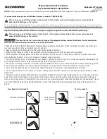
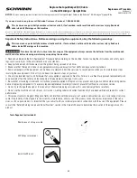
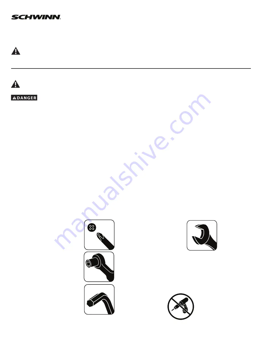
Tools Required (not included)
#2
Phillips
screwdriver
10
mm
Wrench
15
mm
Wrench
14 mm Socket Wrench
4 mm Hex Wrench
6 mm Hex Wrench
Nautilus, Inc., (800) NAUTILUS / (800) 628-8458, www.NautilusInc.com - Customer Service: North America (800) 605-3369, csnls@nautilus.com | outside U.S. www.nautilusinternational.com | Printed in China | © 2013 Nautilus,
Inc. | ® indicates trademarks registered in the United States. These marks may be registered in other nations or otherwise protected by common law. Schwinn and Airdyne are trademarks owned by or licensed to Nautilus, Inc.


