background image

3

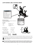
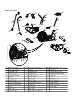
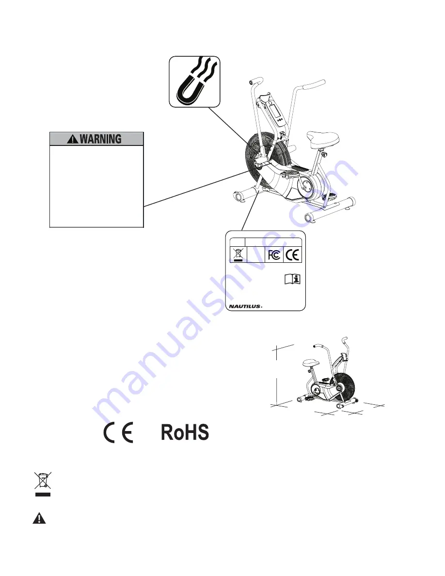
SAFETY WARNING LABELS AND SERIAL NUMBER

Reading the Serial Number

The instructions below show how to decode the information 

contained on the serial number. 

Serial Number

   AAAAAAA 


Nautilus part number (SKU)

   BBB 


Vendor Code

   PPPPPP   


Purchase Order Number

   LL 


Purchase Order Line Number

   CCCCCC  


Unique Identifier

Machine Weight:


115 lbs. (52.2 kg)

Power Requirements:


2 AA Batteries 


  Operating Voltage:   

1.0 - 3.3VDC

Maximum User Weight:


300 lbs. (136 kg)

Regulatory Approvals:  

This product conforms to the applicable EN ISO 20957 International Standards for Stationary Training Equipment, Class S

DO NOT dispose of this product as refuse. This product is to be recycled. For information on the proper method of 

disposal, contact a Nautilus Customer Service Representative. Contact information is available in the Contacts 

section in this manual.

This product, its packaging, and components contain chemicals known to the State of California to cause 

cancer, birth defects, or reproductive harm. This Notice is provided in accordance with California’s Proposi-

tion 65. If you would like additional information, please refer to our website at www.nautilus.com/prop65.
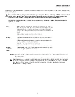
50.9”

(129.2 cm)

25.7”

(65.2 cm)

49.7”

(126.3 cm)

REVISIONS

ECO

REVISION

REV DESCRIPTION

APPROVED

DATE

TITLE.

PART NO.

REV.

SHEET 1 OF 1

SCALE:  1:1

DO NOT SCALE DRAWING

1. ALL ITEMS MUST BE RoHS COMPLIANT

2. ALL DIMENSIONS APPLY BEFORE PLATING OR COATING.

3. REMOVE ALL BURRS, BREAK SHARP EDGES 0.5 MM MAX.

4. ALL MACHINES SURFACES Ra 3.2 uM.

5. ALL APPLICABLE NAUTILUS STANDARDS AND 

    SPECIFICATIONS APPLY.

6. ALL DIMENSIONS ARE IN MILLIMETERS

7. ALL DUAL DIMENSIONS ARE IN INCH

UNLESS OTHERWISE SPECIFIED:

METRIC

THIRD ANGLE 

PROJECTION

INTERPRET DIMENSIONS AND TOLERANCES 
PER ASME Y14.5M - 1994

 2.5

 1.5

 0.75

 0.25

 1°

X.

X.X

X.XX

X.XXX

ANGULAR

C

SIZE

TOLERANCES.

DRAWN

DESIGNED

DATE

METRIC_C_REV G

NAUTILUS, INC.

16400 SE NAUTILUS DRIVE, VANCOUVER, WA 98683

LIFECYCLE

12-20-2011

APPROVALS

- -

- -

- -

WARRANTY ITEM:

LSEVIER

12/20/2011

LSEVIER

B

004-6970

 SN LABEL - AD6

MATERIAL.

COLOR.

  DIE LINE 

  BLACK


Labels must be created from an agency approved tamper proof labeling system  

such as "UL Recognized component marking and labeling system (example:  UL  PGGU2) or equivalent.  

Label and adhesive  must be rated for surface it is applied to (painted metal or ABS plastic), 

Label and adhesive must be rated for 60 degrees C minimum. Labels must meet UL 1647 Permanence of Marking Test.

NOTE:

0000 - SEQUENCIAL SUPPLIER TRACKING NUMBER

REFERANCE  003-9706 FOR ADDITIONAL PLACEMENT GUIDELINES

SERIAL NO. FORMAT

AAAAAAA - SKU (NOT TO EXCEED 12 DIGITS)

BBB - NLS VENDOR CODE (3 DIGITS)

PPPPP - PURCHASE ORDER NUMBER (NOT TO EXCEED 8 DIGITS)

LL- PURCHASE LINE NUMBER (2 DIGITS)

CCCCCC - UNIQUE IDENTIFIER (5 DIGITS) 

MANUFACTURE DATE:

MM/YY - MONTH AND YEAR THE UNIT WAS PRODUCED.

LSEVIER

DRAFTER

40mm

40mm

This document is the property of Nautilus, Inc.  It may not be reproduced in whole or part, provided to third parties, or used for any purposes other than the performance of work for Nautilus, Inc. without written authorization. © Nautilus, Inc. This document is provided in confidence and your acceptance of this document is your agreement to maintain the document in confidence.


A

RELEASE

13410

LSEVIER

12/20/2011

B

ADDED ADDITIONAL INFORMATION FOR COMPLIANCE

?????

LSEVIER

4/2/2012

18225 NE Riverside Parkway, Portland, Or. 97230

www.nautilus.com

Phone:1-800-NAUTILUS

Model: Schwinn®Airdyne®AD6

Rating: NA

Class: SA, HA, 

Maximum User Weight: 300lb (136kg)  

Fitness Equipment

Made in: China

004-6970_B        

0000

Serial Number       

         AAAAAABBBPPPPPPLLCCCCCC

MM/YY

Mfg. Date

ISO

20957


REVISIONS

ECO

REVISION

REV DESCRIPTION

APPROVED

DATE

TITLE.

PART NO.

REV.

SHEET 1 OF 1

SCALE:  1:1

DO NOT SCALE DRAWING

1. ALL ITEMS MUST BE RoHS COMPLIANT

2. ALL DIMENSIONS APPLY BEFORE PLATING OR COATING.

3. REMOVE ALL BURRS, BREAK SHARP EDGES 0.5 MM MAX.

4. ALL MACHINES SURFACES Ra 3.2 uM.

5. ALL APPLICABLE NAUTILUS STANDARDS AND 

    SPECIFICATIONS APPLY.

6. ALL DIMENSIONS ARE IN MILLIMETERS

7. ALL DUAL DIMENSIONS ARE IN INCH

UNLESS OTHERWISE SPECIFIED:

METRIC

THIRD ANGLE 

PROJECTION

INTERPRET DIMENSIONS AND TOLERANCES 
PER ASME Y14.5M - 1994

 2.5

 1.5

 0.75

 0.25

 1°

X.

X.X

X.XX

X.XXX

ANGULAR

C

SIZE

This document is the property of Nautilus, Inc.  It may not be reproduced in whole or part, provided to third parties, or used for any purposes other than the performance of work for Nautilus, Inc. without written authorization. All rights are reserved, including copyrights. 

TOLERANCES.

DRAWN

DESIGNED

DATE

METRIC_C_REV G

NAUTILUS, INC.

16400 SE NAUTILUS DRIVE, VANCOUVER, WA 98683

LIFECYCLE

- -

APPROVALS

- -

- -

- -

WARRANTY ITEM:

L.SEVIER

1/30/2012

L.SEVIER

C

8000072

 GWl AD6 HOME USE 300lbs  

MATERIAL.

COLOR.

DIE LINE

PMS 152


PMS 109

BLACK

WHITE


Labels must be created from an agency approved tamper proof labeling system  

such as "UL Recognized component marking and labeling system (example:  UL  PGGU2) or equivalent.  

Label and adhesive  must be rated for surface it is applied to (painted metal or ABS plastic), 

Label and adhesive must be rated for 60 degrees C minimum. Labels must meet UL 1647 Permanence of Marking Test.

50mm

100.9mm

NPI 13410

A

RELEASE

1/30/2012

LSEVIER

xxxxxxx

B

ADDED WARNING

5/6/2012

LSEVIER

xxxxxxx

C

REMOVED COMMERCIAL WARNINGS

7/19/2012

LSEVIER

•  Gardez les enfants et les animaux de compagnie  
  éloignés de cette machine en tout temps
• 

Déconseillé aux enfants âgés de  


  moins de 14 ans.

•  Lisez et familiarisez-vous avec le Manuel du  
  propriétaire et avec tous les avertissements 
  avant d’utiliser cette machine.
•  Soyez prudent lorsque vous utilisez cet   
  équipement pour ne pas vous infliger de graves  
  blessures.
•  Cette machine supporte un poids maximal de  
  300lbs. (136kg).
•  Remplacez toute étiquette d’avertissement  
  endommagée, illisible ou manquante.
•  Cet appareil est à usage domestique.
•  Lorsque l’appareil est utilisé à domicile,   
  verrouillez-le lorsqu'il n'est pas utilisé.

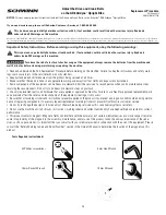
•  Keep children away.
• 

Not intended for use by anyone under  

  14 years of age.

•  Prior to use, read and understand the  
  Owner’s Manual.
•  Injury or death is possible if Caution is  
  not used while using this machine.
•  The maximum user weight for this    
  machine is 300 lbs (136 kg).
•  Replace any “Caution”,  “Warning” or  
  “Danger” label that is illegible,  


  damaged, or removed.
•  This machine is for home use only.
•  Lock the machine when not in operation.

004-8874_C

Summary of Contents for AD6

Page 1: ...lts 13 Part Replacement 3 Replace the Arm Pivot Assembly 16 4 Replace the Crank Belt 20 5 Replace the Drive Belt Fan Assembly 25 6 Replace the Input Output I O Cable 33 7 Replace the Connector Arm 36 8 Replace the Crank Arm 41 9 Replace the Foot Step Pad 43 10 Replace the Shrouds 46 11 Replace the Spindle 48 12 Replace the Speed Sensor 55 Nautilus Inc 800 NAUTILUS 800 628 8458 www NautilusInc com ...

Page 2: ...quest replacement warning stickers or placards from Nautilus customer service Do not try to change the design or functionality of the machine being serviced as this can adversely affect user safety Do not put the machine back in service until all shrouds instructions warning labels and correct functionality have been verified and tested for correct performance This product contains magnets Magneti...

Page 3: ... 25 7 65 2 cm 49 7 126 3 cm 40mm 40mm 18225 NE Riverside Parkway Portland Or 97230 www nautilus com Phone 1 800 NAUTILUS Model Schwinn Airdyne AD6 Rating NA Class SA HA Maximum User Weight 300lb 136kg Fitness Equipment Made in China 004 6970_B 0000 Serial Number AAAAAABBBPPPPPPLLCCCCCC MM YY Mfg Date ISO 20957 50mm 100 9mm Gardezlesenfantsetlesanimauxdecompagnie éloignés de cette machine en tout t...

Page 4: ...t sign of wear or damage After each workout use a damp cloth to wipe your machine and Console free of sweat Note Avoid excessive moisture on the Console Weekly Clean the machine to remove any dust dirt or grime from the sur faces Check for smooth seat operation If needed sparingly apply a thin coating of silicone lube to ease operation Note Do not use petroleum based products Monthly or after 20 h...

Page 5: ...round 10 of their rated power during power up When replacing the batteries make sure the batteries point in the direction shown in the battery bay Note The console uses AA size batteries LR6 Do not mix old and new batteries Do not mix alkaline standard carbon zinc or rechargeable Ni Cd Ni MH etc batteries ...

Page 6: ...ssembly clear of the floor 3 Push the machine into position 4 Carefully lower the machine into position NOTICE Be careful when you move the machine All abrupt motions can affect the computer operation Leveling the Machine The machine needs to be leveled if your workout area is uneven To adjust 1 Place the machine in your workout area 2 Loosen the locking nuts and adjust the levelers until they are...

Page 7: ...Place the machine in a secure location away from children and pets Be aware that the Pedals Handlebars and Resistance Fan are connected and when any of these parts move the others do as well To lock the Fan Assembly 1 Move the Handlebars so that one Handlebar is as close as possible to the Console Support Bar 2 Wrap the Transport and Immobilization Strap T around the Handlebar and the Console Supp...

Page 8: ...eck Speed Sensor Magnet position requires shroud removal Magnet should be in place on pulley Check Speed Sensor As sembly requires shroud removal Speed Sensor Bracket should be aligned with magnet and con nected to data cable Realign sensor if necessary Replace if there is any damage to the sensor or the connecting wire Console displays Lbatt error code Batteries Replace batteries Unit operates bu...

Page 9: ...n nection Pedal should be tightened securely to crank Be sure connec tion is not cross threaded Check crank to axle con nection Crank should be tightened securely to axle Clicking sound when pedaling Check pedal to crank con nection Remove pedals and reattach fully Check Locking Knob Be sure the Locking Knob is clear of Fan Seat post movement Check locking pin Be sure adjustment pin is locked into...

Page 10: ...istics option The Console will display the Total Distance Odo and Total Time Note The upper displayed value shows the total hours followed by the remaining minutes 5 Push START STOP to exit For the next option push the Increase button 6 The Console display shows the Firmware Version prompt Fir The Console will display which Firmware Version is installed in the Speed display field 7 For the next op...

Page 11: ...nk Arm Left EE Fan Cover F Console S Center Plate FF Leveler G Locking Knob T Pedal Left GG Stabilizer Front H Spring Knob U Pulley Crank HH Transport Wheel I Console Support Bar V Speed Sensor Magnet II Shroud Right J Console Cable Upper W Crank Belt JJ Crank Arm Right K Seat X Drive Pulley KK Pedal Right L Seat Post Y Drive Belt M Foot Step Pad Z Speed Sensor Assembly Z BB AA V DD U X Y W CC K F...

Page 12: ...EMENT PROCEDURE SKILL LEVEL Level I Low very little mechanical knowledge or exposure Level II Intermediate some experience with mechanical procedures Level III Advanced knowledgeable about mechanical procedures ...

Page 13: ...are supplied or approved by Nautilus Failure to use Nautilus approved replacement parts can adversely affect the safety and functionality of the equipment creating a risk to users Be sure that all warning stickers and instructional placards applied to the product stay present and in good condition when doing mainte nance or replacing components If necessary request replacement warning stickers or ...

Page 14: ... opposite side of the machine 5 Inspect the Belts The belts should barely be able to be pushed down ward at their mid point Crank Belt 700 800N and the Drive Belt 400N 6 Using a 10 mm wrench adjust the Belt Tension Adjustment Nuts on both sides of the machine Gradually turn it a 1 4 turn on each side Tighten clockwise the Adjustment Nuts to increase the belt tension loosen counter clockwise to dec...

Page 15: ...allation is the reverse procedure Note Be sure when attaching the Crank Arm that all three pieces Crank Arm Crank Cover and Connector Arm are properly aligned before install ing ANY hardware The Crank Cover may have rotated during the Crank Arm removal 10 Final Inspection Inspect your machine to ensure that all hardware is tight and components are properly assembled Do not use until the machine ha...

Page 16: ...t are supplied or approved by Nautilus Failure to use Nautilus approved replacement parts can adversely affect the safety and functionality of the equipment creating a risk to users Be sure that all warning stickers and instructional placards applied to the product stay present and in good condition when doing mainte nance or replacing components If necessary request replacement warning stickers o...

Page 17: ...ds Note To assist with re assembly be aware that the screws indicated with an arrow are Self Tapping Screws 3 Remove the Shroud and Crank Cover To reduce the risk of electrical shock or usage of the equipment always remove the batteries from the machine and wait 5 minutes before cleaning maintaining or repairing the machine Note The images in this procedure show the Left Shroud being removed The p...

Page 18: ...icated screws from the Foot Peg and remove it 5 Remove the Handlebar from the Arm Pivot Assembly 6 Using a 14 mm socket wrench remove the indicated screw from the Connector Arm 7 Disconnect the Connector Arm from the Arm Pivot Assembly Connector Arm Foot Peg Handlebar ...

Page 19: ...ank Arm that all three pieces Crank Arm Crank Cover and Connector Arm are properly aligned before install ing ANY hardware The Crank Cover may have rotated during the Crank Arm removal 10 Final Inspection Inspect your machine to ensure that all hardware is tight and compo nents are properly assembled Do not use until the machine has been fully assembled and inspected for correct performance in acc...

Page 20: ...roved by Nautilus Failure to use Nautilus approved replacement parts can adversely affect the safety and functionality of the equipment creating a risk to users Be sure that all warning stickers and instructional placards applied to the product stay present and in good condition when doing mainte nance or replacing components If necessary request replacement warning stickers or placards from Nauti...

Page 21: ... Self Tapping Screws 3 Remove the Shroud and Crank Cover 4 Repeat procedures on the opposite side of the machine 5 Using a 6 mm hex wrench remove the two indicated screws from the Right Foot Peg and remove it 6 Remove the Handlebar 7 Using a 14 mm socket wrench remove the indicated screw from the Connector Arm 8 Disconnect the Connector Arm from the Arm Pivot Assembly To reduce the risk of electri...

Page 22: ...ch loosen the Belt Tension Adjustment Nut and remove the Eye Bolt Note To assist with re assembly be aware that the Eye Bolt has a slight bend and must be reassembled in the same orientation 11 Repeat the previous step on the opposite side of the machine Eye Bolt Securing Nut Eye Bolt Belt Tension Adjustment Nut ...

Page 23: ...ver the Connector Arm and onto the Crank Pulley Keep fingers out of any pinch opportunities when removing the Pulley Assembly 16 Slightly lift the Pulley Assembly and place the Crank Belt around the small pulley Keep fingers out of any pinch opportunities when removing the Pulley Assembly 17 With the Crank and Drive Belt placed correctly on the Pulley As sembly push it down into the Bracket Attach...

Page 24: ... is the reverse procedure Note Be sure when attaching the Crank Arm that all three pieces Crank Arm Crank Cover and Connector Arm are properly aligned before installing ANY hardware The Crank Cover may have rotated during the Crank Arm removal 21 Final Inspection Inspect your machine to ensure that all hardware is tight and compo nents are properly assembled Do not use until the machine has been f...

Page 25: ...proved by Nautilus Failure to use Nautilus approved replacement parts can adversely affect the safety and functionality of the equipment creating a risk to users Be sure that all warning stickers and instructional placards applied to the product stay present and in good condition when doing mainte nance or replacing components If necessary request replacement warning stickers or placards from Naut...

Page 26: ...re Self Tapping Screws 3 Remove the Shroud and Crank Cover 4 Repeat procedures on the opposite side of the machine 5 Using a 6 mm hex wrench remove the two indicated screws from the Right Foot Peg and remove it 6 Remove the Handlebar 7 Using a 14 mm socket wrench remove the indicated screw from the Connector Arm 8 Disconnect the Connector Arm from the Arm Pivot Assembly To reduce the risk of elect...

Page 27: ...ch loosen the Belt Tension Adjustment Nut and remove the Eye Bolt Note To assist with re assembly be aware that the Eye Bolt has a slight bend and must be reassembled in the same orientation 11 Repeat the previous step on the opposite side of the machine Eye Bolt Securing Nut Eye Bolt Belt Tension Adjustment Nut ...

Page 28: ...ket Keep fingers out of any pinch opportunities when removing the Pulley Assembly 14 Remove the Speed Sensor Magnet from the Speed Sensor Magnet Mount Note Record the distance from the inner edge of the Magnet Mount to the end of the Speed Sensor Magnet for proper replacement position 15 Using a 2 Phillips screwdriver remove the Speed Sensor Magnet Mount from the Frame Pulley Assembly Crank Belt D...

Page 29: ...indicated screws from the Foot Step Pad and remove it 17 Using a 2 Phillips screwdriver remove the screw that was below the Foot Step Pad 18 Using a 2 Phillips screwdriver remove the 2 indicated screws from each side of the Fan Assembly Foot Step Pad ...

Page 30: ...oosen the Fan Tension Adjustment Nut and remove it along with the Eye Bolt Note To assist with re assembly be aware that the Eye Bolt has a slight bend and must be reassembled in the same orientation 22 Repeat procedure on the opposite side of the machine 23 Pulling from the front of the machine remove the Fan Assembly from the Frame Assembly Fan Cage Bracket Eye Bolt Securing Nut Fan Tension Adju...

Page 31: ... Locking Nut by 1 4 turns equally on both sides of the Fan Assembly Do not over adjust 26 Installation is the reverse procedure Note With the Crank and Drive Belt placed correctly on the Pulley Assembly push it down into the Bracket Attach the Eye Bolts oriented correctly with the Belt Tension Adjustment Nuts Gradually tighten the Belt Tension Adjustment Nuts by a full turn alter nating between ea...

Page 32: ...ardware The Crank Cover may have rotated during the Crank Arm removal Final Inspection Inspect your machine to ensure that all hardware is tight and components are properly assembled Do not use until the machine has been fully assembled and inspected for correct performance in accordance with the Owner s Manual Connector Arm Crank Cover Crank Arm ...

Page 33: ... that are supplied or approved by Nautilus Failure to use Nautilus approved replacement parts can adversely affect the safety and functionality of the equipment creating a risk to users Be sure that all warning stickers and instructional placards applied to the product stay present and in good condition when doing mainte nance or replacing components If necessary request replacement warning sticke...

Page 34: ...t Bar Assembly only enough to expose the Speed Sensor Cable Connectors 4 Disconnect the Cables and place the Console Support Bar Assembly on the floor safely out of the work area Note Do not let the Cable fall into the Frame Assembly To reduce the risk of electrical shock or usage of the equipment always remove the batteries from the machine and wait 5 minutes before cleaning maintaining or repair...

Page 35: ...O Cable and place the new I O Cable into the Console Support Bar Assembly Note Be sure the cable does not crimp when being routed into the Con sole Support Bar Assembly 10 Installation is the reverse procedure Note When attaching the Console Support Bar Assembly be sure to slowly pull the Speed Sensor Cable from the Frame Assembly to remove any slack Do not crimp the Cable when attaching the Conso...

Page 36: ...us Failure to use Nautilus approved replacement parts can adversely affect the safety and functionality of the equipment creating a risk to users Be sure that all warning stickers and instructional placards applied to the product stay present and in good condition when doing mainte nance or replacing components If necessary request replacement warning stickers or placards from Nautilus customer se...

Page 37: ...icated screws from the Shrouds Note To assist with re assembly be aware that the screws indicated with an arrow are Self Tapping Screws 3 Remove the Shroud and Crank Cover To reduce the risk of electrical shock or usage of the equipment always remove the batteries from the machine and wait 5 minutes before cleaning maintaining or repairing the machine Note The images in this procedure show the Lef...

Page 38: ...ng the hardware removal 5 Remove the Handlebar from the Arm Pivot Assembly 6 Using a 14 mm socket wrench remove the indicated screw from the Connector Arm 7 Disconnect the Connector Arm from the Arm Pivot Assembly 8 Push and turn the Locking Knob until it is engaged and the Fan Assem bly is locked Connector Arm Foot Peg Handlebar Locking Knob ...

Page 39: ...dware is snug 11 Using a 10 mm wrench gradually tighten the Removal Plate Hard ware equally between the two screws until the Connector Arm discon nects Be sure the area is clear below the Connector Arm except for floor protection Do not try to catch the Connector Arm The Connector Arm will suddenly disconnect and fall 12 Remove the hardware from the Removal Plate using the 10 mm socket and wrench ...

Page 40: ...7 Installation is the reverse procedure Note Be sure when attaching the Crank Arm that all three pieces Crank Arm Crank Cover and Connector Arm are properly aligned before installing ANY hardware The Crank Cover may have rotated during the Crank Arm removal 18 Final Inspection Inspect your machine to ensure that all hardware is tight and compo nents are properly assembled Do not use until the mach...

Page 41: ...rdware that are supplied or approved by Nautilus Failure to use Nautilus approved replacement parts can adversely affect the safety and functionality of the equipment creating a risk to users Be sure that all warning stickers and instructional placards applied to the product stay present and in good condition when doing mainte nance or replacing components If necessary request replacement warning ...

Page 42: ... The Crank Cover may have rotated during the Crank Arm removal 3 Final Inspection Inspect your machine to ensure that all hardware is tight and components are properly assembled Do not use until the machine has been fully assembled and inspected for correct performance in accordance with the Owner s Manual To reduce the risk of electrical shock or usage of the equipment always remove the batteries...

Page 43: ...that are supplied or approved by Nautilus Failure to use Nautilus approved replacement parts can adversely affect the safety and functionality of the equipment creating a risk to users Be sure that all warning stickers and instructional placards applied to the product stay present and in good condition when doing mainte nance or replacing components If necessary request replacement warning sticker...

Page 44: ...emove the indicated screws from the Shrouds Note To assist with re assembly be aware that the screws indicated with an arrow are Self Tapping Screws 3 Remove the Shroud and Crank Cover 4 Repeat procedure on right side of machine To reduce the risk of electrical shock or usage of the equipment always remove the batteries from the machine and wait 5 minutes before cleaning maintaining or repairing t...

Page 45: ... all three pieces Crank Arm Crank Cover and Connector Arm are properly aligned before install ing ANY hardware The Crank Cover may have rotated during the Crank Arm removal 8 Final Inspection Inspect your machine to ensure that all hardware is tight and components are properly assembled Do not use until the machine has been fully assembled and inspected for correct performance in accordance with t...

Page 46: ...re supplied or approved by Nautilus Failure to use Nautilus approved replacement parts can adversely affect the safety and functionality of the equipment creating a risk to users Be sure that all warning stickers and instructional placards applied to the product stay present and in good condition when doing mainte nance or replacing components If necessary request replacement warning stickers or p...

Page 47: ...k Arm Crank Cover and Connector Arm are properly aligned before install ing ANY hardware The Crank Cover may have rotated during the Crank Arm removal 5 Final Inspection Inspect your machine to ensure that all hardware is tight and components are properly assembled Do not use until the machine has been fully assembled and inspected for correct performance in accordance with the Owner s Manual To r...

Page 48: ... approved replacement parts can adversely affect the safety and functionality of the equipment creating a risk to users Be sure that all warning stickers and instructional placards applied to the product stay present and in good condition when doing mainte nance or replacing components If necessary request replacement warning stickers or placards from Nautilus customer service Do not try to change...

Page 49: ... Screws 3 Remove the Shroud and Crank Cover 4 Repeat procedures on the opposite side of the machine 5 Using a 6 mm hex wrench remove the two indicated screws from the Right Foot Peg and remove it 6 Remove the Handlebar 7 Using a 14 mm socket wrench remove the indicated screw from the Connector Arm 8 Disconnect the Connector Arm from the Arm Pivot Assembly To reduce the risk of electrical shock or ...

Page 50: ...rench loosen the Belt Tension Adjustment Nut and remove the Eye Bolt Note To assist with re assembly be aware that the Eye Bolt has a slight bend and must be reassembled in the same orientation 11 Repeat procedures on the opposite side of the machine Eye Bolt Securing Nut Eye Bolt Belt Tension Adjustment Nut ...

Page 51: ...cket Keep fingers out of any pinch opportunities when removing the Pulley Assembly 13 Lift the Pulley Assembly and remove the Crank and Drive Belts from it 14 Remove the Crank Belt by sliding it forward off of the Connector Arm Pulley Assembly Crank Pulley ...

Page 52: ...rdware equally between the two screws until the Connector Arm disconnects Be sure the area is clear below the Connector Arm except for floor protection Do not try to catch the Connector Arm The Connector Arm will suddenly disconnect and fall 18 Remove the hardware from the Removal Plate using the 10 mm socket wrench 19 Remove the indicated bolts from the Drive Pulley and remove it 20 Using a Rubbe...

Page 53: ...inch opportunities when removing the Pulley Assembly 27 Slightly lift the Pulley Assembly and place the Crank Belt around the small pulley Keep fingers out of any pinch opportunities when removing the Pulley Assembly 28 With the Crank and Drive Belt placed correctly on the Pulley Assembly push it down into the Bracket Attach the Eye Bolts oriented correctly with the Belt Tension Adjustment Nuts 29...

Page 54: ...tor Arm are properly aligned before installing ANY hardware The Crank Cover may have rotated during the Crank Arm removal 32 Final Inspection Inspect your machine to ensure that all hardware is tight and compo nents are properly assembled Do not use until the machine has been fully assembled and inspected for correct performance in accordance with the Owner s Manual Connector Arm Crank Cover ...

Page 55: ... away from the product being serviced at all times Make sure that the repair is done in an appropriate work space away from foot traffic and exposure to bystanders Some components of the equipment can be heavy or awkward Enlist the service of a second person when you do maintenance steps involving these components Do not try to do heavy or awkward steps on your own Use only replacement parts and h...

Page 56: ...th re assembly be aware that the four screws toward the rear of the machine are the Self Tapping Screws 3 Remove the Shroud and Crank Cover 4 Using a 6 mm hex wrench remove the two indicated screws from the Console Support Bar Assembly 5 Repeat procedure on the opposite side of the Console Support Bar As sembly To reduce the risk of electrical shock or usage of the equipment always remove the batt...

Page 57: ... Mount Note Record the distance from the the inner edge of the Magnet Mount to the end of the Speed Sensor Magnet for proper replacement position This distance is normally about 1 8 3mm 9 After working the Speed Sensor Grommet loose remove the Speed Sensor Assembly from the Frame Assembly 10 Remove the Grommet from the Cable and attach it to the new Speed Sensor Assembly without damaging the Cable...

Page 58: ...eed Sensor Cable from the Frame Assembly to remove any slack Do not crimp the Cable when attaching the Shroud When attaching the Crank Arm be sure that all three pieces Crank Arm Crank Cover and Connector Arm are properly aligned before installing ANY hardware The Crank Cover may have rotated during the Crank Arm removal 14 Final Inspection Inspect your machine to ensure that all hardware is tight...

Reviews: