31
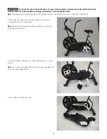
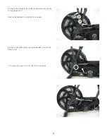
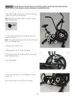
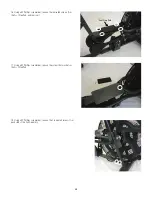
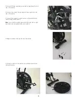
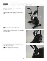
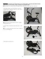
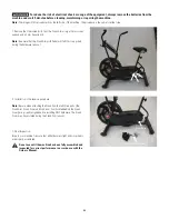
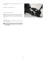
24. Route the Fan Belt into the new Fan Assembly, and over onto the
Fan Assembly Pulley.
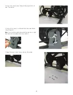
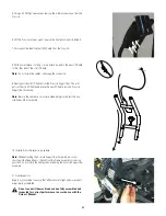
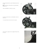
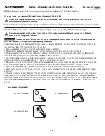
25. Insert the new Fan Assembly with Fan Belt into the Frame Assem-
bly.
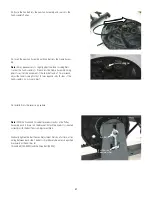
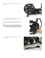
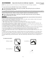
Note:
It may be necessary to slightly adjust the Inner Locking Nuts
to allow the Fan Assembly to fit back into the Frame Assembly. Using
pliers to restrict the movement of the fan shaft and a 17 mm wrench,
adjust the Inner Locking Nut by 1/4 turns equally on both sides of the
Fan Assembly. Do not over adjust.
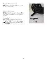
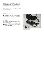
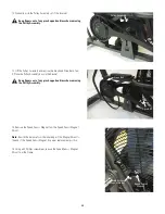
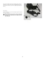
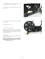
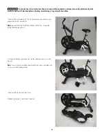
26. Installation is the reverse procedure.
Note:
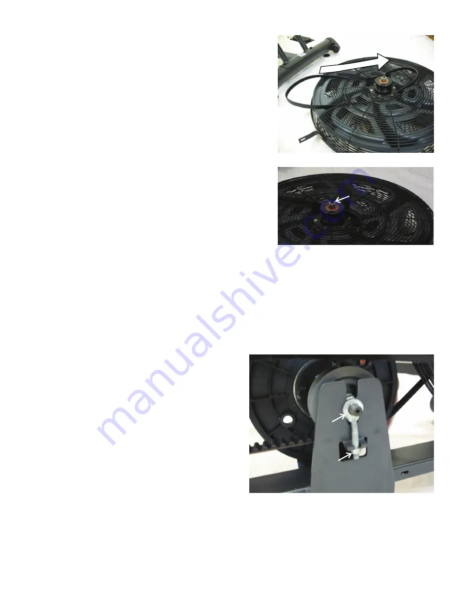
With the Crank and Drive Belt placed correctly on the Pulley
Assembly, push it down into the Bracket. Attach the Eye Bolts (oriented
correctly) with the Belt Tension Adjustment Nuts.
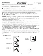
Gradually tighten the Belt Tension Adjustment Nuts by a full turn, alter-
nating between each side. The belts should barely be able to be pushed
downward at their mid-point.
[ Crank Belt (700-800N) and the Drive Belt (400N) ]
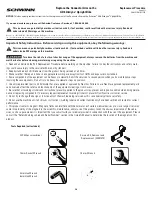
Inner Locking Nut
Eye Bolt
Belt Tension
Adjustment Nut

