53
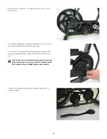
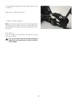
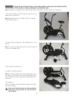
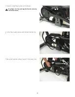
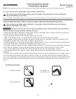
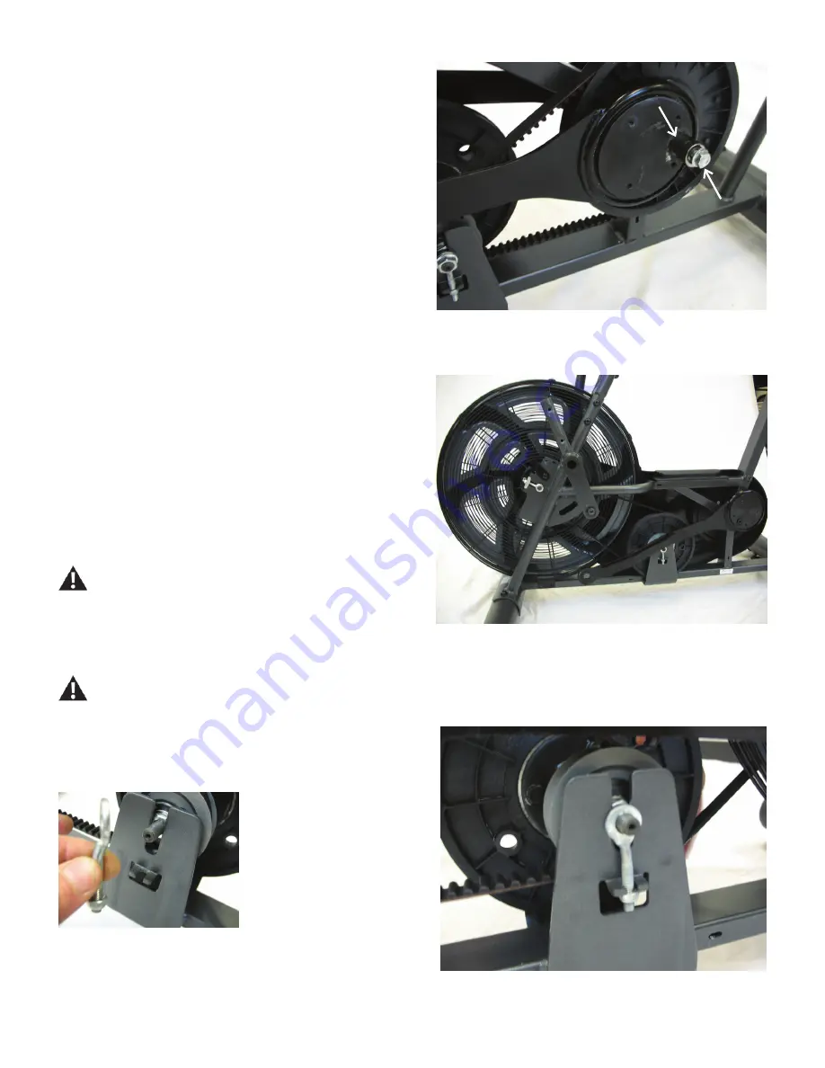
21. To reattach the Connector Arm, insert the Largest Screw from Step 1
with the supplied Spacer into the Connector Arm.
22. Using a 14 mm socket wrench, tighten the Largest Screw with the
Spacer fully.
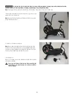
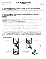
23. Installation is the reverse procedure.
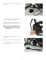
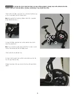
24. Once fully tightened, remove the Largest Screw with Spacer from the
Connector Arm.
25. Repeat procedure on other side.
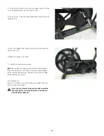
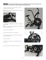
26. Route the Crank Belt over the Connector Arm and onto the Crank Pulley.
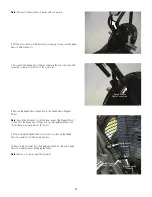
Keep fingers out of any pinch opportunities when removing
the Pulley Assembly.
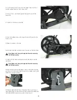
27. Slightly lift the Pulley Assembly and place the Crank Belt around the
small pulley.
Keep fingers out of any pinch opportunities when removing
the Pulley Assembly.
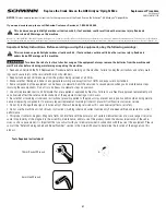
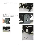
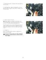
28. With the Crank and Drive Belt placed correctly on the Pulley Assembly,
push it down into the Bracket. Attach the Eye Bolts (oriented correctly) with
the Belt Tension Adjustment Nuts.
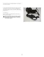
29. Gradually tighten the Belt Tension Adjustment Nuts by a full turn, al-
ternating between each side. Continue until the Crank Belt (700-800N) and
the Drive Belt (400N) can barely be pushed at their mid-point.
Eye Bolt
Belt Tension Ad-
justment Nut
Largest Screw
Spacer

