56
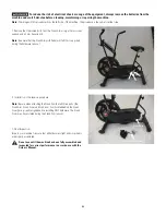
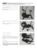
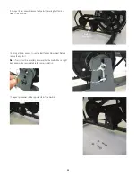
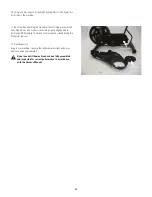
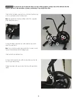
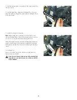
1. Remove the 3 indicated screws (with arrows) from the Crank Arm using
a 14 mm socket wrench and a 4 mm hex wrench
Note:
Be aware that the Crank Arm and Pedal will fall if not supported
during the hardware removal.
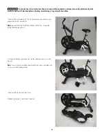
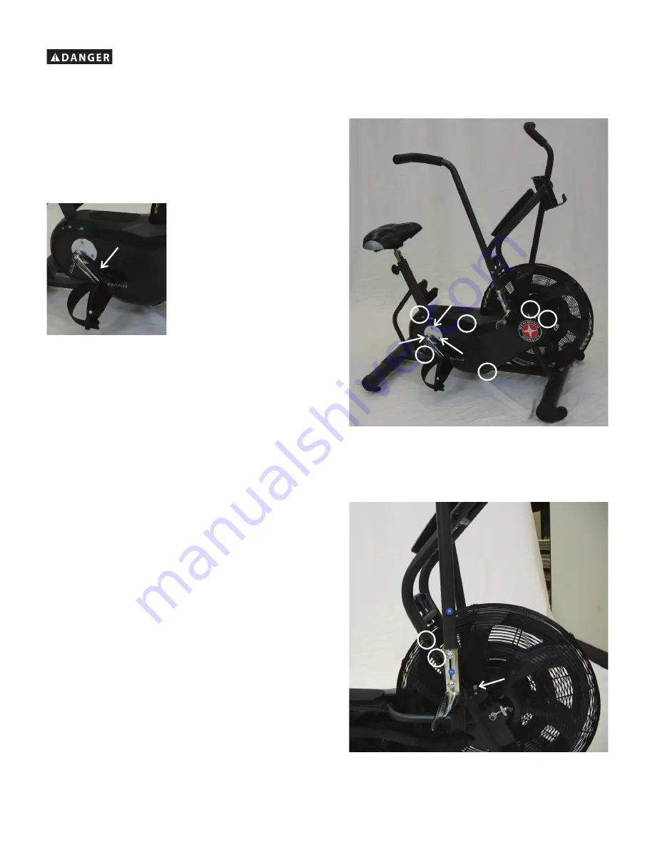
2. Using a #2 Phillips screwdriver, remove the indicated screws (with
circles) from the Shrouds.
Note:
To assist with re-assembly, be aware that the four screws toward
the rear of the machine are the Self-Tapping Screws.
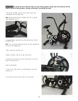
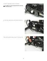
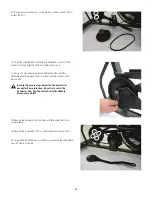
3. Remove the Shroud and Crank Cover.
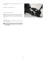
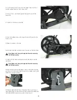
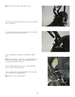
4. Using a 6 mm hex wrench, remove the two indicated screws from the
Console Support Bar Assembly.
5. Repeat procedure on the opposite side of the Console Support Bar As-
sembly.
To reduce the risk of electrical shock or usage of the equipment, always remove the batteries from the
machine and wait 5 minutes before cleaning, maintaining or repairing the machine.
Speed Sensor
Magnet
Crank Arm

