Bravo G4 17 / Bravo G4 22 / Bravo G4 28
EN
21
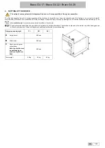
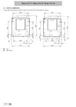
4.2. COMPARTMENT DIMENSIONS FOR BUILT-IN INSTALLATION
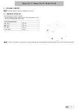
When installing the steriliser inside a cabinet, you must provide adequate space all around the device to provide effective ventilation as well as an opening
in the back (
D
) - 180 sq.cm - that, in addition to allowing the passage of the power cord, will also provide an adequate air flow and the optimum cooling of
the heat exchanger.
Mount the rear spacers supplied to ensure that the steriliser is placed at the correct distance from the wall.
The compartment where the steriliser will be installed must have the following minimum dimensions:
COMPARTMENT
DIMENSIONS
CHAMBER VOLUME 17-22-28 L
A
Height
470 mm
B
Width
520 mm
C
Depth
670 mm
Compartment dimensions lower than those shown may compromise the correct circulation of air around the device and may not
provide adequate cooling, with the consequent deterioration of performance and/or possible damage.
If the main switch is inaccessible when installed in the compartment, use an electric plug that incorporates an on/off switch.
Do not remove the upper cover nor any other external part. The device must be completely installed in the compartment.
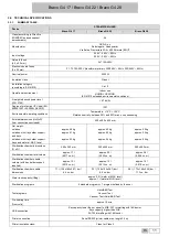
Please refer to appendix “technical characteristics” for complete technical data.
4.3. GENERAL PRECAUTIONS FOR INSTALLATION
To ensure a correct operation of the device and/or avoid risky situations, respect the following
warnings
:
•
Install the steriliser on a flat and perfectly horizontal surface;
•
Make sure that the support surface is strong enough to support the device weight (about 90 kg, complete with water in hydrostatic test configuration);
•
Leave adequate space for ventilation all around the steriliser, in particular in the rear area;
•
If the device is built-in into a cabinet, be sure to respect the warnings in the previous paragraph, avoiding any obstructions of the air intakes;
•
Do not install the steriliser too close to tubs, sinks or similar places, avoiding contact with water or liquids. This could cause short circuits and/or potentially
dangerous situations for the operator;
•
Do not install the steriliser in excessively humid or poorly ventilated environments;
•
Do not install the machine in environments with flammable and/or explosive gasses or vapours;
•
Install the device so that the supply cable is not bent or squeezed.
•
Supply cable must freely run all the way to the electrical outlet;
•
Install the device so that any external filling/drainage tubes are not bent or squeezed.
4.4. POWER SUPPLY
The electrical system to which the steriliser will be connected must match the electrical characteristics of the device.
Plate data are shown in the TECHNICAL CHARACTERISTICS table and on the back of the machine.

