SD-438 EU EN R5
3
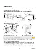
intake is important and failure to provide the required space may cause overheating of the dryer motor
and/or compromise drying efficiency.
Note 5: The unit should be installed as supplied as every part of the unit has a purpose to guarantee trouble
free operation.
In particular, the legs of the HYDR
IM
G4 have been designed to distribute the weight of the
machine to the chassis of the unit and to ensure a leveled installation. If units are installed without legs, the unit
may start to leak from the door. Therefore, the legs of the unit cannot be removed for installation
purposes.
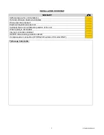
Pre Installation Checklist
The following items are required to be in place before installation begins.
Description
!
/
"
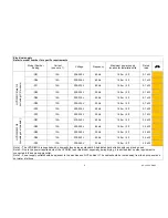
Hot water/Cold water/Reverse Osmosis (RO) water feed with G
¾
” or DN 20 shut off
valve
(washing machine fitting)
Distance of water connections
•
Maximum distance from installation less than 1.50 m / 5 ft
Water inlet pressure
•
HYDR
IM
C61wd G4: 1 to 10 bar / 14 to 145 psi
•
HYDR
IM
M2 G4: 2 to 5 bar / 29 to 72 psi
Minimum water supply for each inlet
•
HYDR
IM
C61wd G4: 2.5 L/min
•
HYDR
IM
M2 G4: 4.5 L/min
Note 1: If hot water is not available then it must be possible to attach a ‘Y’ fitting to the cold water feed valve
so that both machine pipes can be connected to the cold supply. The machine will not work with only one
supply attached as it requires pressure in both supplies to activate the feed pressure switches. Please note
that cold fill only will increase cycle times.
Note 2: Water feeds should be adjacent to the machine and not behind it so that the shut off valves may be
accessed in case emergency isolation is required and to ensure unit can be inserted fully under the work
surface.
Drain outlet
!
/
"
•
Maximum distance from installation is 1.50 m / 5 ft with supplied drain hose
•
The maximum length of an extended drain hose should not exceed 3.30 m / 10.8
ft.
•
Drain should be no more than 1 m / 3.2 ft above the base of the HYDR
IM
unit.
•
‘P’ trap spur connection (preferred method)
OR
standpipe connection
•
Accommodate
¾
” drain hose
•
Material of drain must withstand 95°C fluid
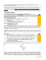
Note 1: The preferred method of connection of the HYDR
IM
to the drain is by the use of a ‘spurred’ ‘P’ trap
fitting.
Note 2: The waste connection pipe is clamped on to the spur by the clips provided with the HYDR
IM
.
Wherever possible, if the HYDR
IM
is located close to a sink unit, then this method should be used. If the
HYDR
IM
is not close to a sink unit and a ‘P’ trap cannot be used, then a standpipe with ‘U’ bend fitting can
be used.
This must be a dedicated standpipe. Under no circumstances should any other equipment

