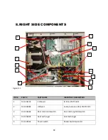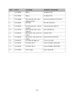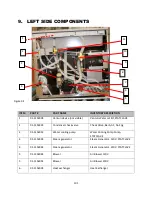
100
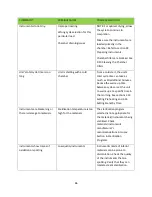
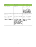
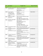
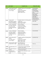
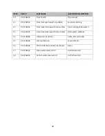
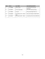
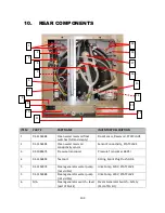
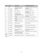
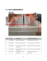
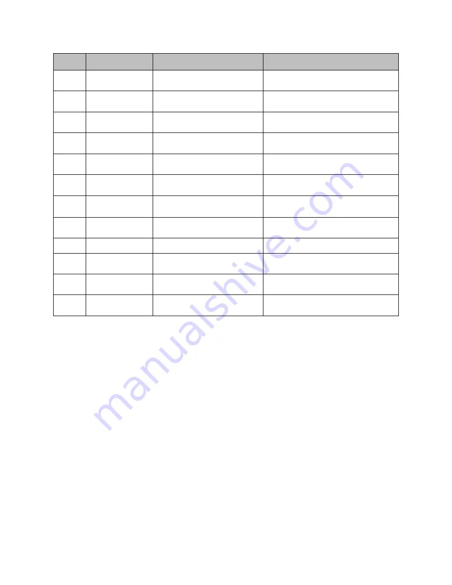
ITEM
PART #
PART NAME
INVENTORY DESCRIPTION
6
01-115404S
Blower
Air Blower 120V
6
01-115405S
Blower
Air Blower 230V
7
01-115468S
Solenoid valve VDB – drain
steam generator
Valve Drain Boiler Kit, STATCLAVE
8
01-110505S
EMI filter
EMI Filter 20A/250V
9
01-115467S
Solenoid valve VEC – exhaust
chamber
Valve Exhaust Chamber Kit
10
01-115470S
Solenoid valve VFW – clean
water fill
Valve Fill Water Kit
11
01-115417S
Band heater relay switch (not
visible)
Relay Kit 120V
11
01-115418S
Band heater relay switch (not
visible)
Relay Kit 230V, STATCLAVE
12
01-103472S
Fuse 15A 250V (Pkg of 2)
Fuses 15 A (2 Pcs)
13
01-115414S
Controller board
Control PCB 120V, STATCLAVE
13
01-115415S
Controller board
Control PCB 230V, STATCLAVE
14
01-113266S
Power supply
Power Supply 24V
Summary of Contents for STATCLAVE G4
Page 5: ...5 Diagram of key systems and components...
Page 6: ...6...
Page 17: ...17 Checking package contents...
Page 18: ...18 Positioning a unit Unit dimensions and operating environment...
Page 20: ...20 Direct to drain connection recommended...
Page 21: ...21 Connecting to a waste bottle...
Page 22: ...22 Connecting to the Internet Connecting to a wired network Connecting to a wireless network...
Page 23: ...23...
Page 25: ...25 Connecting an auxiliary pump...
Page 28: ...28...
Page 30: ...30 Starting and stopping a cycle...
Page 50: ...50 Registering for online access...
Page 51: ...51 First start up...
Page 52: ...52...
Page 58: ...58 Draining the unit for cleaning and shipping...
Page 61: ...61 Replacing the bacteriological filter Replacing the door seal...
Page 75: ...75...
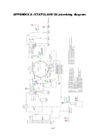
Page 107: ...107 APPENDIX A STATCLAVE G4 plumbing diagram...
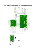
Page 108: ...108 APPENDIX B STATCLAVE G4 electrical schematic...

