70
NOTE: The
POV
offset will be adjusted again at Step 26 of the calibration process when the unit reaches a
pressure (vacuum) value in the region of
20kPa (30kPa or less)
.
17.
On completion of the vacuum phase, the unit will go back to atmospheric pressure. Check the readings between
the unit’s pressure display (
P
) and the pressure reference meter. The two readings should still be within
0.5Kpa
.
STAGE 5. Checking your reference meter values using the steam saturation table
18.
The unit will now start to heat up to 120°C for the first time. This is the first pressure pulse. It will be
followed by a vacuum pulse and then the pressure and temperature will begin to increase again.
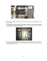
CAUTION! The Teflon tubing connecting the test port to the pressure reference meter will
become hot.
19.
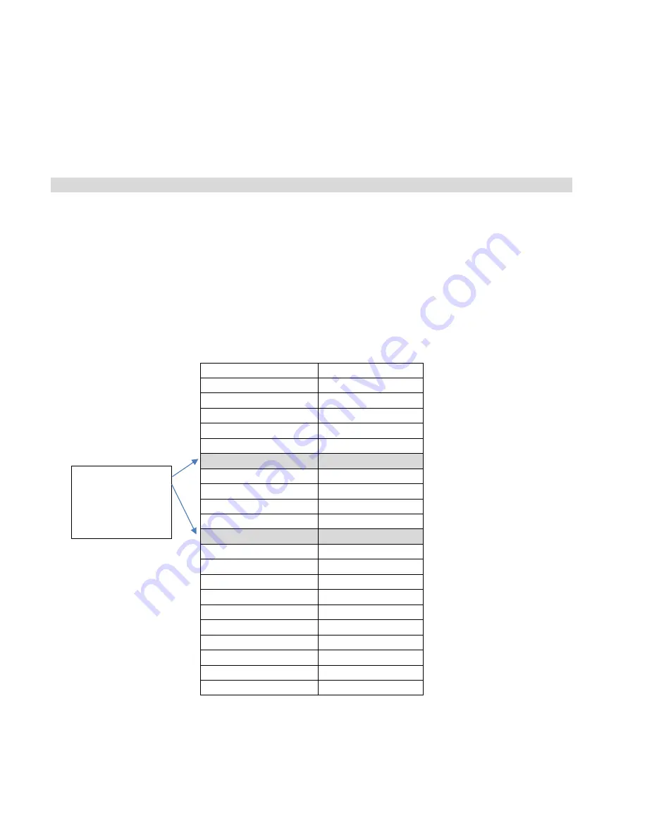
When the reference meter reaches 125°C, you can verify that the steam saturation level is correct by
checking the temperature and pressure values on your reference meters against the table below. Check
again at 130°C.
To check the values, read the temperature on your reference meter and make sure that the pressure
reference meter is reading a value that is within 3 kPa from the corresponding pressure value in the
table. For example, at 125°C your corresponding pressure value should be no lower than 229.24 and
no higher than 235.24.
Temperature (°C)
Pressure (kPa)
120
198.67
121
205.05
122
211.59
123
218.3
124
225.18
125
232.24
126
239.47
127
246.89
128
254.5
129
262.29
130
270.28
131
278.46
132
286.85
133
295.43
134
304.23
135
313.23
136
322.45
137
331.88
138
341.54
139
351.43
140
361.54
20.
If your reference meters DO show that your temperature and pressure values match with the steam
saturation table, continue to the next step.
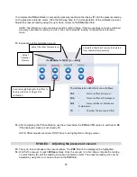
Check reference
meter values
here
Summary of Contents for STATCLAVE G4
Page 5: ...5 Diagram of key systems and components...
Page 6: ...6...
Page 17: ...17 Checking package contents...
Page 18: ...18 Positioning a unit Unit dimensions and operating environment...
Page 20: ...20 Direct to drain connection recommended...
Page 21: ...21 Connecting to a waste bottle...
Page 22: ...22 Connecting to the Internet Connecting to a wired network Connecting to a wireless network...
Page 23: ...23...
Page 25: ...25 Connecting an auxiliary pump...
Page 28: ...28...
Page 30: ...30 Starting and stopping a cycle...
Page 50: ...50 Registering for online access...
Page 51: ...51 First start up...
Page 52: ...52...
Page 58: ...58 Draining the unit for cleaning and shipping...
Page 61: ...61 Replacing the bacteriological filter Replacing the door seal...
Page 75: ...75...
Page 107: ...107 APPENDIX A STATCLAVE G4 plumbing diagram...
Page 108: ...108 APPENDIX B STATCLAVE G4 electrical schematic...

