74
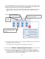
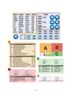
The device screen is divided into four groups (see image below).
Section A is for monitoring all systems.
The values displayed here are generated in real time.
Section B is for checking the heating systems.
To verify the functioning of either the steam generator (TSG)
or the top and bottom band heaters (TBHT and TBHB), you can use the arrows to the right to increase the
temperature in that component to a specific target temperature and then watch the corresponding reading
in Section A to see if the component successfully reaches the target temperature.
Section C is for checking the individual functioning of valves, pumps and the heat exchanger fan.
Press on a
button to activate that individual component or press the buttons in a specific sequence to simulate an
operating condition.
Section D locks and unlocks the door.
There are 3 microswitches that control the door functioning. Door
closed (DCL), door latched (DLA) and door locked (DLK) are listed in Section A along with their ON/OFF values
to show that the microswitches are functioning correctly.
Summary of Contents for STATCLAVE G4
Page 5: ...5 Diagram of key systems and components...
Page 6: ...6...
Page 17: ...17 Checking package contents...
Page 18: ...18 Positioning a unit Unit dimensions and operating environment...
Page 20: ...20 Direct to drain connection recommended...
Page 21: ...21 Connecting to a waste bottle...
Page 22: ...22 Connecting to the Internet Connecting to a wired network Connecting to a wireless network...
Page 23: ...23...
Page 25: ...25 Connecting an auxiliary pump...
Page 28: ...28...
Page 30: ...30 Starting and stopping a cycle...
Page 50: ...50 Registering for online access...
Page 51: ...51 First start up...
Page 52: ...52...
Page 58: ...58 Draining the unit for cleaning and shipping...
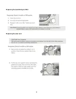
Page 61: ...61 Replacing the bacteriological filter Replacing the door seal...
Page 75: ...75...
Page 107: ...107 APPENDIX A STATCLAVE G4 plumbing diagram...
Page 108: ...108 APPENDIX B STATCLAVE G4 electrical schematic...


