77
Investigating a leak: how to perform a positive pressure test
There are 3 methods to pressurize the system with air to search for leaks in the plumbing system.
Method 1 uses the air intake tube, method 2 uses the test port and method 3 uses a solenoid valve.
Method 1: Using the air intake tube
1.
Remove the left and right panels. Remove the top screws on the rear panel/condenser and
leave it in the open position.
2.
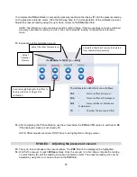
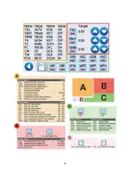
On the LCD screen, go to the technician menu. Go to Diagnostic Tools →Device Status/Tests
menu. On the device screen, press the VDB valve button to close this valve.
3.
Close and latch the door then use the lock icon on the device screen to lock the door.
4.
On the right side of the unit, disconnect the silicone tubing from the biological air filter inlet
port.
5.
Insert the nozzle of a compressed air gun into the silicone tubing and add air to increase the
pressure in the chamber.
6.
On the device screen you will see sensor readings on left side of the display. The ‘Pressure
Chamber’ (PC) value is the current pressure in the chamber.
7.
Raise the Pressure Chamber (PC) value to 270 kPa. IMPORTANT! Do not exceed 380 kPa because
this will trigger the pressure relief valve.
8.
Turn off the compressed air and disconnect it from the silicone tubing. It may take up to 5
minutes for the air pressure reading to stabilize. If you notice a rapid drop in air pressure then
you have a leak, but fluctuations in air pressure are common until it can stabilize.
9.
Using a soap and water mixture in a spray bottle, spray the tube and valve connections to look
for bubbles.
On the right side, check:
•
Solenoid valve VDB
•
Solenoid valve VFC
•
NOTE: Solenoid valve VFW does not need to be checked because it is part of the filling system.
On the left side, check:
•
Solenoid valve VVC
•
Venturi check valve
•
Vacuum check valve
On the rear, check:
•
Solenoid valve VFB
•
Pressure relief valve
•
Pressure sensor
•
Thermocouple fittings
•
Steam generator fittings (3)
Summary of Contents for STATCLAVE G4
Page 5: ...5 Diagram of key systems and components...
Page 6: ...6...
Page 17: ...17 Checking package contents...
Page 18: ...18 Positioning a unit Unit dimensions and operating environment...
Page 20: ...20 Direct to drain connection recommended...
Page 21: ...21 Connecting to a waste bottle...
Page 22: ...22 Connecting to the Internet Connecting to a wired network Connecting to a wireless network...
Page 23: ...23...
Page 25: ...25 Connecting an auxiliary pump...
Page 28: ...28...
Page 30: ...30 Starting and stopping a cycle...
Page 50: ...50 Registering for online access...
Page 51: ...51 First start up...
Page 52: ...52...
Page 58: ...58 Draining the unit for cleaning and shipping...
Page 61: ...61 Replacing the bacteriological filter Replacing the door seal...
Page 75: ...75...
Page 107: ...107 APPENDIX A STATCLAVE G4 plumbing diagram...
Page 108: ...108 APPENDIX B STATCLAVE G4 electrical schematic...

