7
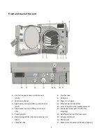
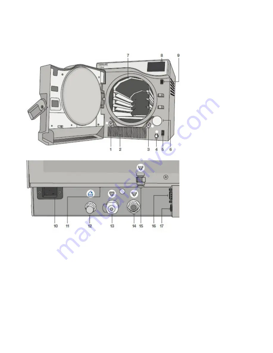
Front and back of the unit
1.
Venturi reservoir drain quick-connect
(OUT)
2.
Warm air exhaust
3.
Clean water reservoir drain quick-connect
(OUT)
4.
Clean water reservoir fill quick-connect
(IN)
5.
Power switch
6.
Bacteriological filter (bacteria-retentive air
filter)
7.
Chamber rack
8.
Touchscreen
9.
USB port
10.
Power cord input
11.
Ethernet port (not visible)
12.
Auto fill port for clean water reservoir
13.
Condenser drain port (to drain for
shipping)
14.
Overflow drain port for reservoirs
15.
Exhaust drain port
16.
RS232 port
17.
Power port for external fill pump (option)
Summary of Contents for STATCLAVE G4
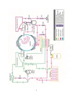
Page 5: ...5 Diagram of key systems and components...
Page 6: ...6...
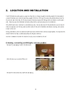
Page 17: ...17 Checking package contents...
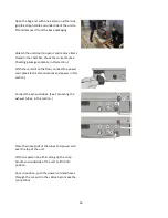
Page 18: ...18 Positioning a unit Unit dimensions and operating environment...
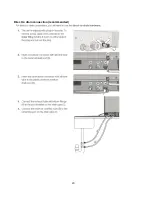
Page 20: ...20 Direct to drain connection recommended...
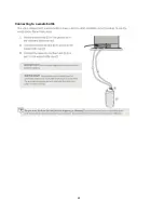
Page 21: ...21 Connecting to a waste bottle...
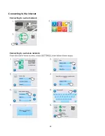
Page 22: ...22 Connecting to the Internet Connecting to a wired network Connecting to a wireless network...
Page 23: ...23...
Page 25: ...25 Connecting an auxiliary pump...
Page 28: ...28...
Page 30: ...30 Starting and stopping a cycle...
Page 50: ...50 Registering for online access...
Page 51: ...51 First start up...
Page 52: ...52...
Page 58: ...58 Draining the unit for cleaning and shipping...
Page 61: ...61 Replacing the bacteriological filter Replacing the door seal...
Page 75: ...75...
Page 107: ...107 APPENDIX A STATCLAVE G4 plumbing diagram...
Page 108: ...108 APPENDIX B STATCLAVE G4 electrical schematic...

