background image

Page 120

STAT

IM 2000/2000S 

Service Guide

96-106775  Rev 5.0

 
6.  Cover Assembly

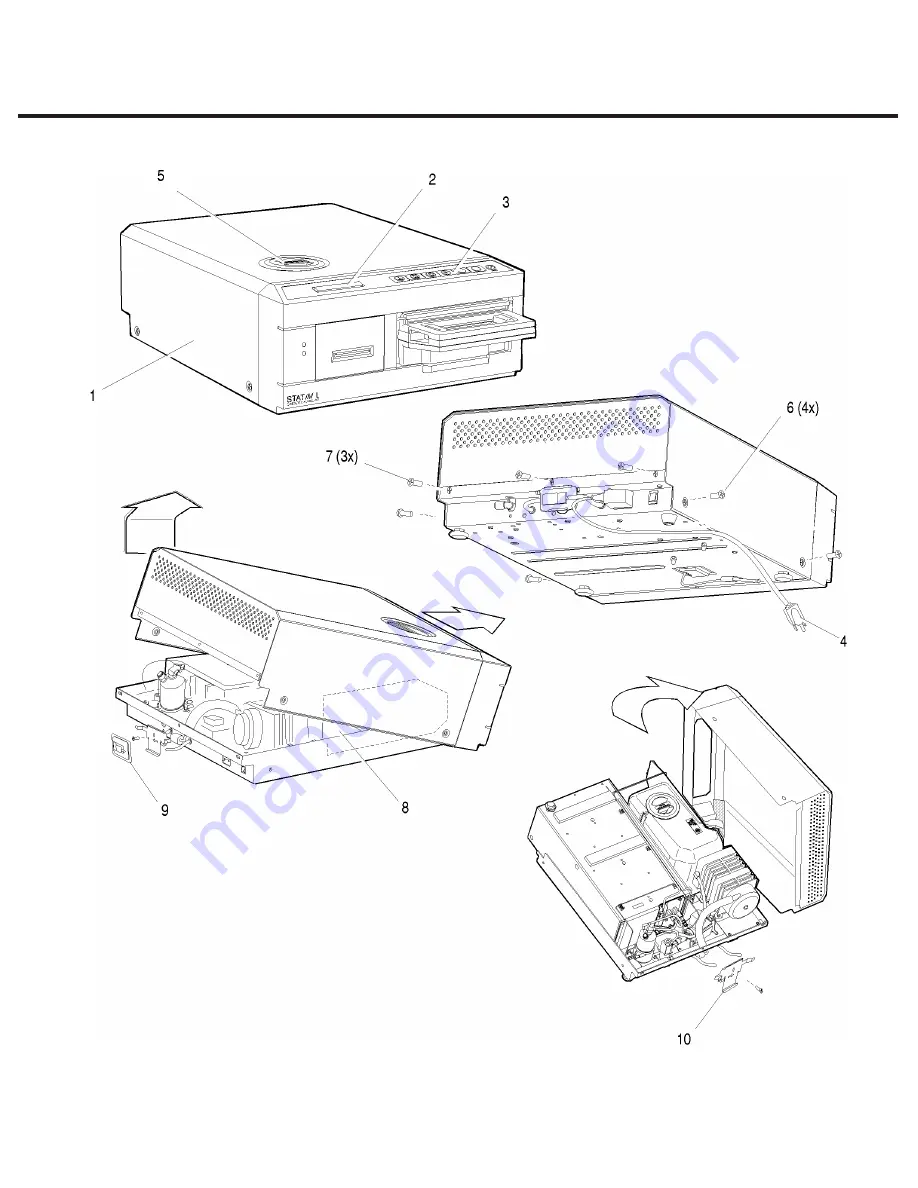
Figure 1

  STAT

IM

 5000/5000S/5000 G4 Service Guide

1.  cover 
2.  LCD  
3.  keypad 
4.  power cord (not shown) 
5.  reservoir cap 
6.  screws for side of unit (both sides)
7.  screws with lockwashers
8.  Controller Board
9.  bacteria-retentive air filter (if present)
10.  filter bracket (if present)

Summary of Contents for STATIM 5000S

Page 1: ...STATIM 5000 5000S 5000 G4 Cassette autoclave Service Manual STAT IM 5000 Service Manual 96 106775 Rev 5 0 Copyright 2012 SciCan Ltd All rights reserved...

Page 2: ...x controllers 47 For units with 7 x controllers with service menu 48 Using the service menu on the Statim G4 Rev 7 controller board 64 Troubleshooting cycle faults 65 Cycle Fault Numbers and descripti...

Page 3: ...edure 164 Performing filter maintenance 164 Performing internal pump filter maintenance 165 Performing water reservoir filter maintenance 167 Performing inline filter maintenance 168 Performing pump t...

Page 4: ...generator 236 Pressure relief valve 236 Checking the pressure relief valve 237 Removing and replacing the pressure relief valve 237 12 Printer and Data Logger 241 Printer 242 Removing and replacing t...

Page 5: ...protective bonding impedance test ground continuity must be performed on the STATIM when the work is completed and after the cover has been returned to the unit The STATIM is heavy Exercise caution an...

Page 6: ...st ground continuity must be performed on the STATIM when the work is completed and after the cover has been returned to the unit PROTECT THE UNIT Use only steam process distilled water in the STATIM...

Page 7: ...S class no pressure transducer for the non S class The details in the matrix further below will help you identify units based on their factory specifications Identifying Software Versions To identify...

Page 8: ...502R1xx S502R2xx Aluminium Internal 2 x 5 x N A N A 2 5000 2004 2005 S502R4xx Stainless Steel 6 x N A N A 3 5000 2005 2007 S502R5xx Aluminium Internal 6 x N A 3 5000 2007 S502R6xx Aluminium External 7...

Page 9: ...d side Rectangular microprocessor plus EPROM W1 jumper for calibration Blue pressure interface printer connector Typical features Revision number bottom right hand side Square microprocessor plus EPRO...

Page 10: ...dentified as below Figure 2 Aluminum steam generator with internal thermocouple 1995 2004 Stainless steel steam generator 2004 2005 Typical features 70 p s i pressure relief valve PRV no ring pull The...

Page 11: ...ouple a k a ALEX boiler 2005 present Typical features 43 5 p s i pressure relief valve PRV ring pull on S models no ring pull on non S models Thermocouple clamped to underside of steam generator Blank...

Page 12: ...est ground continuity must be performed on the STATIM when the work is completed and after the cover has been returned to the unit PROTECT THE UNIT Use only steam process distilled water in the STATIM...

Page 13: ...103087S 7 Calibration cassette SciCan 5000 All models SciCan Part 01 106366S Generic reference devices for calibration 8 Calibrated digital thermometer with K type probe 9 Calibrated digital voltmeter...

Page 14: ...nnector connect to Controller Board header P1 Sample equipment set up for calibration of S unit 1 Calibration cassette 2 Digital voltmeter 3 Digital reference thermometer with thermocouple Fluke 51 wi...

Page 15: ...ice manual If only the display and button functions are being used connect the LCD cable 6 to Controller Board connector P3 the keypad cable 7 to Controller Board connector P4 and power the STATIM ON...

Page 16: ...if appropriate monitoring devices a special calibration cassette must be used The calibration cassette allows a technician to independently monitor the temperature and pressure inside the cassette en...

Page 17: ...ertified calibration laboratory A number of meters are recommended by SciCan and are referenced as follows For non S unit calibration The following reference meters are recommended for use with 01 103...

Page 18: ...use the flexible thermocouple in the future SciCan advises you to consult the digital thermometer s manual for setting a temporary offset if required The above probe is 3 2mm 1 8 diameter Technicians...

Page 19: ...probe as follows Meter without data logging capabilities PTEC X X 4 4A Pressure Module HQS2 B A A 400 kPa A Temperature Module HQS RT1 PT 100 RTD Probe Pt 100 PT5 Notes These product references are ve...

Page 20: ...e probe into the fitting as far as it will go A slight resistance will be felt as the probe passes through the seal Tighten the clamp nut until a steam air tight seal is achieved DO NOT OVERTIGHTEN NO...

Page 21: ...ure reference meter s The temperature fitting right hand fitting when facing the front of the cassette is fitted with a compression fitting that consists of a body clamp nut and conical compression wa...

Page 22: ...eference meter then the 1 16 1 6mm compression fitting complete will need to be removed from the extension piece attached to the cassette and replaced with the 1 8 3 175mm compression fitting from the...

Page 23: ...an adaptor to attach BSP devices such as hypodermic pressure fittings See Figure 9 below This adaptor is not used with the standard SciCan pressure tube and should be removed from the cassette extens...

Page 24: ...E PTFE tape should be used when assembling these parts to ensure a steam tight seal Figure 11 Male Swagelok Quick Connect fitting and cassette extension fitting assembly Attaching the pressure tube to...

Page 25: ...sealing Quick Connect QC4 female connector see Figure 13 on either end These connectors attach to the male Quick Connect fitting shown in Figure 10 above Figure 13 Swagelock Quick Connect QC4 female c...

Page 26: ...ed with the cassette Attaching the tube to the connector is as described in the section above however the second male fitting will need to be installed onto the pressure reference meter prior to attem...

Page 27: ...pe as shown is essential to ensure the connection is free from steam leaks If the joint leaks steam can enter the transducer and damage the unit internally Install assembly from previous step onto ext...

Page 28: ...Guide 96 106775 Rev 5 0 2 Tools Maintenance Schedules Procedures and Testing STATIM 5000 5000S 5000 G4 Service Guide Figure 16 below shows the meter pressure transducer and pressure tube attached to...

Page 29: ...1 8 NPT female to NPT male adaptor for this device see Figure 17 for assembly Figure 17 Heise meter with Swagelok fitting attached to pressure module Insert and tighten the Swagelok fitting into the...

Page 30: ...dures and Testing STATIM 5000 5000S 5000 G4 Service Guide Figure 18 below shows the meter with temperature probe and pressure tube ready to attach to a calibration cassette Figure 18 Heise hand held c...

Page 31: ...ion or failure occurs and should not need to be changed routinely on an annual basis These may be identified during service and changed as appropriate Consumable items such as seals and filters may re...

Page 32: ...age Note pay particular attention to the rear hinge and rear wall of the base as damage in this area may cause steam leakage even if a new seal is fitted Fit new cassette seal Diagnostics and Testing...

Page 33: ...heoretical pressure are within 1 kPa This is important for the efficient balance of the control and validation circuits Failure to achieve this may result in unnecessary cycle failures Re check steam...

Page 34: ...ine Scrub the inside with a cleaning pad designed for use with Teflon coated surfaces After removing all traces of the detergent treat interior surfaces of the cassette with the STAT DRI Plus drying a...

Page 35: ...can be positioned over a container when the unit is lowered back to the work surface Remove the stopper 4 from the end of the drain tube and allow the water to drain from the reservoir When water no...

Page 36: ...d cause damage to the unit Changing the air filter and bacteria retentive filter where fitted Never re use an old filter Never run the unit without a clean filter in place After each sterilization cyc...

Page 37: ...the back of the compressor 7 Remove the plate 2 Remove and discard the old filter 3 Install the new filter 8 and secure the compressor plate to the rear of the compressor using the screw retained fro...

Page 38: ...t tube 4 from the bacteria retentive filter 2 and remove the filter from the filter bracket 3 Note the orientation of the arrow mark on the filter and bracket 2 When the filter is free of the bracket...

Page 39: ...nel This is intentional as the seal compresses into the channel when fitted to ensure the correct pressure on the base of the cassette when closed Locate and align the steam inlet holes in the seal by...

Page 40: ...or a mild disinfectant to clean all outside surfaces Do not use solvents or harsh chemicals Shipping the unit If you must ship your STATIM follow these directions 1 Drain the reservoir See Draining t...

Page 41: ...t you have the following files on the USB Drive firmware ini Firmware Folder SL00R100_4_100_CAA29608 sci cp bat firmware ini 3 With the unit powered OFF insert the USB drive loaded with the firmware u...

Page 42: ...s 1 From the TOOLS page click on the LOCAL CONTROL tab 2 Click on the start button to start a local connection It will open up a page that mirrors your STATIM unit s touchscreen so that it can be cont...

Page 43: ...EW ACCOUNT link complete the form and click on the SUBMIT FORM link The system will send a confirmation email to verify the account Once confirmed the account will be ready to use With a valid user na...

Page 44: ...500 V Dwell Time 2 Seconds W High 3 5mA W Low 0 05mA Frequency 60 HZ Continuity OFF STATIM G4 5000 units W Ramp 2 Seconds W Volt 1500 V Dwell Time 2 Seconds W High 6 0mA W Low 0 05mA Frequency 60 Hz C...

Page 45: ...of dissolved solids in the steam process distilled water used in the STATIM unit Use only steam process distilled water having 5 ppm or less dissolved solids or a conductivity of less than 10 S cm Fo...

Page 46: ...performed on the STATIM when the work is completed and after the cover has been returned to the unit PROTECT THE UNIT Use only steam process distilled water in the STATIM The STATIM contains electron...

Page 47: ...spect the bacterial filter and compressor filter for signs of contamination Perform component tests to determine the operational status of the solenoid valve pump and compressor if fitted Perform a pu...

Page 48: ...as opposed to using a control box Certain information provided in this menu may be used to assist in diagnostics Using the service menu on the STATIM Classic Rev 7 controller board The service menu ca...

Page 49: ...indicated sub menu item as indicated by the cursor Stop button Exits the menu and returns the unit to operational mode Calibration Time Date setup Language setup Unit ID setup Set cycle counter Lock...

Page 50: ...inutes date month and year After entering the menu the hour value will be highlighted Using the cycle buttons to select and change the selected field s value 1 To increase a field s value press the UN...

Page 51: ...t cycle counter sub menu This function allows the technician to change the cycle count of the unit This is designed to be used when a complete controller change is necessary and the customer needs to...

Page 52: ...ked it must be all or none The cycles available on all S class units mentioned above are as follows Solid Unwrapped 134 C 3 5 min N Hollow Unwrapped 134 C 3 5 min S Hollow Unwrapped 134 C 18 min S Hol...

Page 53: ...selected cycles 13 Press the Unwrapped button to unlock the cycles 14 The display will now show the following for a short time And then it will display all of the available cycles 7 cycles 15 Turn uni...

Page 54: ...out making changes power the STATIM OFF 16 For unlocking the cycles on a unit with locked cycles follow steps 6 to 10 Upon entering locking unlocking mode the display will show And display only the se...

Page 55: ...acceptable error 10 0uS G GG Water conductivity circuit gain Default value 1 00 Units with sensor and WITH float LL L Lower value threshold No water threshold Values lower than this triggers Refill re...

Page 56: ...et this condition should it change as a result of a software or controller change follow these steps 1 The UNWRAPPED or WRAPPED keys will switch the screen display to ON or OFF depending on the openin...

Page 57: ...to the service menu 3 Pressing the STOP key will return the unit to the operational menu Devices Test ON OFF Screen display when in Devices Test ON OFF sub menu This function on revision 7 STATIM unit...

Page 58: ...atmospheric pressure This allows the pressure sensor atmospheric offset value to be read without entering calibration mode No changes can be made to the offset value in this sub menu 1 To return to t...

Page 59: ...units with the correct software will show the pressure transducer type in this sub menu 1 To return to the service menu press the RUBBER PLASTICS button 2 To return to the operational menu press the S...

Page 60: ...TIM units is OFF To activate repeater mode proceed as follows 1 The UNWRAPPED or WRAPPED keys will both switch the screen display to ON or OFF depending on the opening display 2 The RUBBER PLASTICS ke...

Page 61: ...nd return the unit to the operational menu Change Password This function will allow you to change the default password Unwrapped Wrapped Rubber and Plastics Stop to a new key button sequence When ente...

Page 62: ...alternative is YES To activate NVRAM restoration proceed as follows 1 The UNWRAPPED or WRAPPED keys will both switch the screen display to YES 2 The RUBBER PLASTICS key will action your selection and...

Page 63: ...his sub menu There are two specific pump types identified by this sub menu the ULKA pump fitted to later machines and the INVENSYS or SCICAN pump fitted to earlier units The pumps are NOT interchangea...

Page 64: ...k Cycles Firmware Upgrade NVRAM Tools Water Pump Type Time Date DST On Off Recent Printouts Time 12 24 Date Format Language Unit No Water Quality Serial Number Printer Type Baud Rate End of Line CR LF...

Page 65: ...ycle fault numbers and descriptions appropriate to ALL Statim 2000 and 5000 units with revision 2 x 5 x 6 x and 7 x type controller boards with revision 1 xx 2 xx 4 xx 5 xx and 6 xx software as approp...

Page 66: ...seconds remaining in the cycle If a request to pump water occurs outside of 2 minutes 44 seconds Check Cassette 5 occurs This indicates a substantial steam leak from the cassette a contaminated steam...

Page 67: ...nt but related issue For example a blown thermal fuse is only symptomatic of a boiler overheat and not necessarily the cause of the failure which may be through poor water delivery so it would be usef...

Page 68: ...hin a time out period Major steam leak Overloaded cassette Incorrect chamber calibration 3 The cassette has failed to pressurize and achieve a temperature of 110 C within a time out period This may be...

Page 69: ...ture 6 C greater than the chamber during the sterilizing phase of a cycle Obstruction caused by o Seal misalignment o Foreign material in the seal channel Calibration imbalance boiler thermocouple to...

Page 70: ...solenoid valve Check Vref is 2 520V 0 001V all software revisions OTHER THAN revision 6 xx 9 Not used 10 During conditioning purging the cassette temperature has failed to drop to115 C during the Unwr...

Page 71: ...ed solenoid coil Faulty seal installation 17 18 Not used 19 For software rev R1xx R2xx and R4xx the steam generator calibration is invalid For software rev R5xx and R6xx the validation thermocouple ca...

Page 72: ...alve Check Vref is 2 520V 0 001V 26 ii The sterilization phase has failed to start within 3 minutes of the cassette reaching the sterilization temperature Note the unit has to fail on 3 consecutive cy...

Page 73: ...n the system 51 For the Rubber and Plastics cycle the chamber temperature rose more than 4 C above the sterilization temperature allowing for measurement error i e Tchm 125 C Sticking solenoid valve c...

Page 74: ...balance pressure transducer or chamber thermocouple Sticking solenoid valve closed Failed solenoid coil Blocked cassette exhaust duct Obstructed exhaust tubing kink Poor air removal 60 For a 134 C cyc...

Page 75: ...tion imbalance pressure transducer or chamber thermocouple Poor air removal during conditioning exhaust blockage Not able to generate steam Steam leak in the system 65 For a 134 C cycle the theoretica...

Page 76: ...Being executed at the wrong time This routine should only run when in Boiler calibration mode This may occur if the microprocessor operates erratically due to electrical noise 81 The state buffer poi...

Page 77: ...is occurs when a new controller board or microprocessor has been installed This may also happen when the unit has been subjected to a strong static discharge corrupting the memory Re calibrate the cha...

Page 78: ...nts See also section 12 of this manual CYCLE ABORTED This error message is displayed on the printout only followed by the message NOT STERILE as a result of the operator pressing the STOP button to st...

Page 79: ...Page 79 STATIM 2000 2000S Service Guide 96 106775 Rev 5 0 3 Troubleshooting Cycle Faults STATIM 5000 5000S 5000 G4 Service Guide...

Page 80: ...ntinuity must be performed on the STATIM when the work is completed and after the cover has been returned to the unit PROTECT THE UNIT Use only steam process distilled water in the STATIM The STATIM c...

Page 81: ...y other hot surfaces This may cause improper values on the temperature readout There are specific error messages cycle faults for these board software types which can be found in the Troubleshooting C...

Page 82: ...er board 3 SELECT knob 4 Digital voltmeter 5 Vref potentiometer 6 Calibration cassette 7 Thermocouple 8 Digital thermometer 9 TC ADJ potentiometer 10 Calibration jumper connection 11 Calibration jumpe...

Page 83: ...ART button An asterisk will appear next to the message CALIBRATING 4 If the asterisk does not appear press the STOP button on the control box twice to reset the unit Turn the power switch OFF then ON...

Page 84: ...ch the sterilization temperature of 134 C 4 The temperature displayed on the LCD needs to match the temperature displayed on the digital thermometer 5 To change the temperature display on the LCD adju...

Page 85: ...OPERATING UNITS WITH THE STAINLESS STEEL BOILER AND REVISION 5 XX SOFTWARE IS FOR OPERATING THE ALUMINIUM EXTERNAL ALEX BOILER CALIBRATION HOWEVER IS THE SAME FOR BOTH Neither boiler requires calibra...

Page 86: ...ller board 3 SELECT knob 4 Digital voltmeter 5 VREF potentiometer 6 Calibration cassette 7 Thermocouple 8 Digital thermometer 9 TC ADJ potentiometer 10 Calibration jumper connection 11 Calibration jum...

Page 87: ...ion cycle press and release the UNWRAPPED cycle button on the control box and then press the START button The STATIM will run a regular UNWRAPPED cycle but continue to show calibration information on...

Page 88: ...the asterisk does not appear press the STOP button on the control box twice to reset the unit Turn the power switch OFF then ON again Hold down the UNWRAPPED cycle button on the control box and press...

Page 89: ...the Troubleshooting Cycle Faults section Boiler calibration is not required as these units are fitted with a separate validation thermocouple These units may be calibrated with the cover in place OR u...

Page 90: ...ter 5 Calibration cassette 6 Thermocouple 7 Digital thermometer Figure 3 1 2 3 4 5 6 7 NOTE The cover MAY be removed and the control box attached if deemed appropriate but the unit can be calibrated w...

Page 91: ...utton The STATIM will run a regular UNWRAPPED cycle but continue to show calibration information on the LCD 9 Wait for the chamber to reach the sterilization temperature of 134 C TTT 10 The temperatur...

Page 92: ...START button An asterisk will appear next to the validation thermocouple offset value CVO to indicate that a Validation Assy calibration cycle is running 7 If the asterisk does not appear press the ST...

Page 93: ...ction Boiler calibration is not required as these units are fitted with a separate validation thermocouple These units may be calibrated with the cover in place OR using the control box There is NO re...

Page 94: ...ration cycle select Calibration in the Calibration submenu and calibration with start automatically The STATIM will run a regular UNWRAPPED cycle but continue to show calibration information on the LC...

Page 95: ...e the temperatures displayed on the LCD and the digital thermometer for 30 seconds The temperatures registered should remain within 0 2 C of one another If not make adjustments using the arrow keys 5...

Page 96: ...self calibration to complete 6 The temperature within the chamber will rise to the sterilization temperature Wait until sterilization phase of the calibration cycle ends automatically 7 The offset va...

Page 97: ...Page 97 STATIM 2000 2000S Service Guide 96 106775 Rev 5 0 4 STATIM 5000 Calibration STATIM 5000 5000S 5000 G4 Service Guide...

Page 98: ...tinuity must be performed on the STATIM when the work is completed and after the cover has been returned to the unit PROTECT THE UNIT Use only steam process distilled water in the STATIM The STATIM co...

Page 99: ...charge ESD Observe appropriate safeguards when calibrating There are specific error messages cycle faults for these board software types These can be found in the Troubleshooting Cycle Faults section...

Page 100: ...e tube to the test cassette Self locking couplings 6 Install the calibration jumper to Controller Board pins marked W1 7 Locate TC ADJ and Vref potentiometers 1 Control box 2 Controller board 3 SELECT...

Page 101: ...e steam generator offset value 4 If the asterisk does not appear press the STOP button on the control box twice to reset the unit Turn the power switch OFF then ON again 5 Hold down the UNWRAPPED cycl...

Page 102: ...red chamber pressure is increased or decreased in 0 5 kPa steps Each press of the UNWRAPPED button adds 0 5 kPa and each press of the WRAPPED button subtracts 0 5 kPa 16 Allow the chamber to reach the...

Page 103: ...adjustment indicates that one or more of the following components may be faulty Chamber thermocouple Pressure sensor Pressure interface board Controller board Thermocouple amplifier or A to D convert...

Page 104: ...n In calibration mode no error messages are displayed IMPORTANT REVISION 4 XX SOFTWARE IS FOR OPERATING UNITS WITH THE STAINLESS STEEL BOILER AND REVISION 5 XX SOFTWARE IS FOR OPERATING THE ALUMINIUM...

Page 105: ...the pressure tube to the test cassette Self locking couplings 6 Install the calibration jumper to controller board pins marked W1 7 Locate TC ADJ and Vref potentiometers 1 Control box 2 Controller boa...

Page 106: ...n place and turn the power switch ON The LCD will read for example Where PPP P actual chamber pressure in kPa PO chamber pressure hexadecimal offset value TTT T theoretical pressure calculated from th...

Page 107: ...e reference meter s reading The CO field will then show the new chamber temperature offset IMPORTANT NOTE When the initial pressure and temperature readings have been adjusted and to ensure equilibriu...

Page 108: ...icient time to compare them If you are confident that the temperature readings are still within 0 25 C then the unit is in equilibrium and the calibration has finished If the readings are outside of t...

Page 109: ...not required on these units These units may be calibrated with the cover in place OR using the control box as all adjustments are made with the WRAPPED or UNWRAPPED keys on the relevant keypad There i...

Page 110: ...ration cassette 6 Thermocouple 7 Digital thermometer 8 Pressure meter Figure 3 STATIM 5000 5000S 5000 G4 Service Guide 1 11 2 3 5 6 7 8 Note The cover MAY be removed and the control box attached if de...

Page 111: ...t next item in the menu Wrapped Key Select previous item in the menu Rubber and Plastics Key Enter current selection Toggle using keypad through the menu selection to reach Calibration option and pres...

Page 112: ...ou are confident that the readings are stable the chamber thermocouple offset CO can now be adjusted using the wrapped and unwrapped keys until the reading on the LCD display as displayed in the CCC C...

Page 113: ...ings CCC C as follows Press the Rubber and Plastics key The PO value will now STOP flashing and the CO value will now flash Use the wrapped and unwrapped keys to correct the TTT T value so that it is...

Page 114: ...on mode no error messages are displayed Boiler calibration is not required on these units These units may be calibrated with the cover in place OR using the control box as all adjustments are made usi...

Page 115: ...ord to continue default password is 7919 9 From the service menu select Calibration IMPORTANT NOTES Remember the steam generator thermocouple does NOT require calibration The VREF does not need adjust...

Page 116: ...adjusted while it is flashing 4 During calibration the unit will run a normal cycle 5 Allow the chamber to reach the sterilization temperature As pressure builds in the chamber check for leaks in the...

Page 117: ...ill not within 1 kPa of each other further adjustment may be undertaken by modifying the TTT T value The theoretical pressure reading TTT T and actual chamber temperature reading CCC C are directly re...

Page 118: ...nd continuity must be performed on the STATIM when the work is completed and after the cover has been returned to the unit PROTECT THE UNIT Use only steam process distilled water in the STATIM The STA...

Page 119: ...t by a single screw This filter must be disconnected and the bracket 10 removed before the cover can be removed If the bacteria retentive air filter is present proceed as in section 2 Filters on the S...

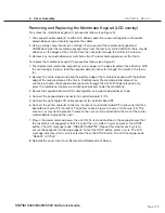
Page 120: ...embly Figure 1 STATIM 5000 5000S 5000 G4 Service Guide 1 cover 2 LCD 3 keypad 4 power cord not shown 5 reservoir cap 6 screws for side of unit both sides 7 screws with lockwashers 8 Controller Board 9...

Page 121: ...d unplug the power cord 5 Carefully lift the cover from the work surface While rotating the cover slide it forward until the fascia clears the Controller Board and the front of the armature 6 Tilt the...

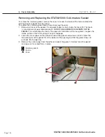
Page 122: ...ng and Replacing the Fascia To remove the fascia 1 proceed as follows see Figure 2 1 The fascia is attached to the cover 3 using seven plastite screws 4 Remove and retain the screws 2 A bead of silico...

Page 123: ...cessed area on the fascia Carefully lower the membrane into place while continuing to draw the keypad cable connector through the slot With finger pressure only press the membrane into place eliminati...

Page 124: ...106775 Rev 5 0 6 Cover Assembly STATIM 5000 5000S 5000 G4 Service Guide 1 membrane keypad 2 keypad cable 3 LCD cable 4 fascia 5 LCD 6 slot 7 Controller Board 8 printer cable 9 Pressure Interface Board...

Page 125: ...e LCD cable 8 and the keypad cable 7 are on the same side of the cover Note Do not press down in the middle of the LCD assembly Apply pressure in the areas immediately adjacent the mounting holes only...

Page 126: ...775 Rev 5 0 6 Cover Assembly 1 LCD 2 fascia 3 printer module 4 membrane keypad 5 screws countersink 6 captive fasteners 7 keypad cable 8 LCD cable 9 controller board 10 pressure transducer interface F...

Page 127: ...wo on each side 4 and then three with lockwashers 5 at the rear of the unit using a 2 Phillips screwdriver Note that the center screw on the rear of the unit also attaches the bracket for the bacteria...

Page 128: ...2000 Service Guide Cover Assembly n 1 Cover n 3 Line filter Reservoir cap n 4 Side screws both sides n 5 Screws with lockwashers n 6 Bacteria retentive air filter n 7 Filter bracket n 9 Controller bo...

Page 129: ...rom the work surface While rotating the cover slide it forward until the fascia clears the controller board 8 and the front of the armature 6 Tilt the front of the cover down and the rear of the cover...

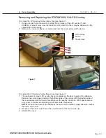
Page 130: ...rom the adhesive side of the gasket Carefully install the gasket making sure it is seated firmly in place Page 23 STATIM 5000 G4 Service Guide Removing and Replacing the Armature Gasket To remove the...

Page 131: ...of the LCD 2 Reconnect the power cord Power the unit ON and test the touchscreen 3 3 Reinstall the cover Page 24 STATIM 5000 G4 Service Guide Removing and Replacing the LCD Overlay To remove the LCD o...

Page 132: ...om the fascia 6 and discard it 3 The colour LCD touchscreen is held in place with two sided adhesive tape If it does not come off easily put a small screwdriver in the PCB connector cable slit and pus...

Page 133: ...Assembly STATIM 5000 5000S 5000 G4 Service Guide Page 26 STATIM 5000 G4 Service Guide Cover Assembly n 1 Flexible PCB connector n 3 Colour LCD touchscreen n 3 LCD controller board n 3 Hinged catch n 3...

Page 134: ...water tight seal between the fascia and cover during manufacturing Remove the fascia and any silicon residue remaining on the cover 5 Discard the old fascia The fascia is made of recyclable polycarbon...

Page 135: ...Page 135 STATIM 2000 2000S Service Guide 96 106775 Rev 5 0 6 Cover Assembly STATIM 5000 5000S 5000 G4 Service Guide...

Page 136: ...ty must be performed on the STATIM when the work is completed and after the cover has been returned to the unit PROTECT THE UNIT Use only steam process distilled water in the STATIM The STATIM contain...

Page 137: ...Blue pressure interface printer connector Typical features Revision number bottom right hand side Square microprocessor plus EPROM W1 jumper for calibration Blue pressure interface printer connector...

Page 138: ...servoir float old Water quality probe Cassette microswitch CHAMBER ground terminal BOILER ground terminal Pressure transducer interface S units or Printer connection non S units Water pump Water pump...

Page 139: ...re no validation thermocouple is present there may be a printer cable attached in this socket Remove this if present Disconnect the steam generator thermocouple wires 2 from controller board terminal...

Page 140: ...nplug the thermocouple connectors 6 There are three from non S boiler chamber and validation and two for S class boiler and chamber Unplug the float connector 7 on units where the water quality and fl...

Page 141: ...sitions labeled PROBE 9 or the float sensor leads if present from terminal positions labeled FLOAT 10 Note that on later units a third ground wire 11 may be present as well as the two PROBE wires 4 Di...

Page 142: ...er board J1 terminal 12 Each lead is numbered with a corresponding J1 designation See Table B Table B Controller Board High Voltage J1 Connector Marking Fuse Value Device Signal Wire Colour COMP J1 10...

Page 143: ...the screw is tightened Ensure the wires are seated securely behind the respective washers Reconnect the steam generator thermocouple wires to the controller board terminal positions BOILER Y and R 2...

Page 144: ...on some non S units where no validation thermocouple is present a printer cable is attached in this socket Replace this if present Rev 3 x 4 x units DO NOT have this socket 8 A dielectric strength tes...

Page 145: ...cable 8 6 Disconnect the wires to the speaker 9 To replace the colour LCD controller board follow these steps see Figure 5 1 Re connect the wires to the speaker 9 2 Re connect the Ethernet port cable...

Page 146: ...ice Guide Cover Assembly n 1 LCD controller board n 3 DC power source cable n 3 DC power source n 3 PCB connector n 3 Hinged catch n 3 Clips n 3 USB cable n 3 Ethernet port cable n 3 Speaker connect n...

Page 147: ...erse the removal instructions use hot glue to secure speaker Cover Assembly Figure 6 n 1 USB port cable n 3 LCD controller board n 3 USB port assembly n 3 Speaker n 3 Tabs 1 2 3 4 5 1 2 4 3 5 STATIM 5...

Page 148: ...er and remove cable by cutting the cable tie To replace reverse the removal instructions Removing and Replacing the Ethernet port To remove the Ethernet port first remove the cover and place it upside...

Page 149: ...x 4 x controller boards all have the following main processor configuration Revision 2 x 5 x controller boards also have a supplementary EEPROM located near to the main processor Rev 3 x 4 x DO NOT h...

Page 150: ...re Programmed EEPROM where fitted Before removing or replacing the devices observe appropriate electrostatic discharge precautions for the work area and technician Ensure that the unit is powered OFF...

Page 151: ...he board in the lower right hand corner Determine the rated voltage of the unit by examining the serial number label Use this information to find the appropriate microprocessor replacement kit 2 a For...

Page 152: ...follows see Figure 19 1 Turn the power switch OFF and unplug the unit 2 Disconnect the microswitch leads 1 from the controller board 2 terminal block positions labelled CASSIN J4 1 AND J4 2 J3 1 and...

Page 153: ...ated Carefully insert the cassette If the solenoid valve clicks before the cassette is fully inserted the microswitch needs to be adjusted If the solenoid valve does not click after the cassette is fu...

Page 154: ...Cords STATIM 5000 units are fitted with detachable power cords which are modular and plug into a panel mounted A C inlet receptacle or receptacle line filter in the back of the chassis STATIM 5000 500...

Page 155: ...ord from the panel mount A C inlet receptacle 3 Replacing refitting a Detachable Power Cord Use replacement cords with appropriate safety agency ratings and approvals only To replace reinstall a detac...

Page 156: ...ce Guide Position N Position P 1 detachable line cord not shown 2 power switch 3 A C inlet receptacle 4 line filter 5 four screws obscured 6 compressor assembly 7 chassis 8 thermocouple leads 9 white...

Page 157: ...tch out of the chassis wall Replacing refitting the A C Power Switch To replace the power switch 2 follow these steps See Figure 21 1 From a position at the rear of the unit orient spade terminals 1a...

Page 158: ...remove the filter Replacing refitting the Receptacle Line Filter To replace refit a line filter 4 proceed as follows See Figure 21 1 Insert the line filter in the opening in the chassis 7 The P and N...

Page 159: ...the chassis 6 To replace the LCD DC power source reverse the removal instructions Page 32 STATIM 5000 G4 Service Guide Removing and Replacing the LCD DC power source To remove the LCD DC power source...

Page 160: ...ty must be performed on the STATIM when the work is completed and after the cover has been returned to the unit PROTECT THE UNIT Use only steam process distilled water in the STATIM The STATIM contain...

Page 161: ...n Pump The SciCan pump is generally factory fitted to units with revision 2 x 5 x 6 x and some early 7 x controller boards from 1995 up to mid 2008 It has a similar footprint to the Fluid O Tech pump...

Page 162: ...inlet tube 1 from the top of the steam generator 2 using a 3 8 inch wrench 2 Connect the disconnected end of the steam generator inlet tube to the pump tester 3 Do not cross thread the fittings Do not...

Page 163: ...ters The following pump parameters are valid for this procedure Unit Voltage Rating 100 V 50Hz 100 V 60 Hz 110 V 60 Hz 230 V 50 Hz For units fitted with alluminum steam generators the following times...

Page 164: ...cated internally in the pump In 2007 SciCan removed these two filters due to the implementation of the water reservoir filter in 2006 and subsequent introduction of the in line filter in 2007 The in l...

Page 165: ...If the pressure transducer 4 is present disconnect the transducer connector 5 See PressureTransducer 4 Remove the compression nut 6 holding the compressor output tube 7 to the compressor and disconne...

Page 166: ...fitting to the pump body inlet fitting Ensure that the rubber seal is in place Tighten the fitting finger tight and using a 9 16 inch wrench tighten one half turn ONLY so as not to damage the interna...

Page 167: ...ents 17 Apply a small amount of Teflon tape or pipe thread compound to the external thread of the collar and insert the fitting collar sub assembly into the pump body outlet fitting Finger tighten onl...

Page 168: ...sterilization cycle and observe filter and tubes for leaks Check LCD read outs for messages indicating cycle status 11 The in line filter kit can be retro fitted and is available as part 01 106637S an...

Page 169: ...ue will likely be in the region of a difference of 0 0040 larger For example a 0 0245 tube fitted to an aluminium steam generator may be 0 0285 on a stainless steel steam generator If as a result of a...

Page 170: ...Parameters chart the pump is performing correctly If the water level reaches the top of the line marked MIN in less than that time or if the water level does not reach the top of the line marked MIN w...

Page 171: ...4 one at each end of the pump mounting bracket 5 and one holding the inlet tube 6 to the pump inlet fitting 7 Do not nick the tubing while cutting the cable ties Remove the rubber tube from the inlet...

Page 172: ...om the diode plug 2 and retain for reassembly 6 Detach the diode plug from the pump body If the pump has been removed or after detaching the diode plug 1 Remove the rubber boot 4 from the diode plug 2...

Page 173: ...Teflon tube to the inlet fitting 11 on top of the steam generator 10 finger tight Tighten this nut using a 3 8 inch wrench Do not overtighten 4 Re attach the diode plug 2 using the diode plug screw 1...

Page 174: ...ing 3 Do not nick the tubing while cutting the cable tie Remove the rubber tube from the inlet fitting and clamp or stop the end of the tube securely 5 Using a 3 8 inch wrench remove the compression n...

Page 175: ...ATIM again once the work is completed and the cover has been returned to the unit 7 Make sure there is sufficient steam process distilled water in the reservoir and activate the pump using the Control...

Page 176: ...eed as follows see Figure 19 The unit should be disconnected from the electricity supply before performing this procedure as the unit needs to be turned on it s side to detach the reservoir securing s...

Page 177: ...e T fitting 8 Secure the tube using a cable tie 4 5 Fill the reservoir with steam process distilled water TIP Touch the leads of the water quality sensor assembly to an earthed point to discharge any...

Page 178: ...Page 178 STATIM 2000 2000S Service Guide 96 106775 Rev 5 0 8 Water Pumps Reservoir and Compressor STATIM 5000 5000S 5000 G4 Service Guide Figure 19...

Page 179: ...ontroller board Checking the conductivity sensor To check the conductivity sensor proceed as follows 1 Power the unit OFF and disconnect the sensor leads from controller board connector positions J4 3...

Page 180: ...ets older affects the accuracy of the sensor and the WATER QUALITY NOT ACCEPTABLE message appears in the LCD display even though nothing is actually wrong with the water This is rare but can occur in...

Page 181: ...ll the pump as described in the section above Installing reinstalling the SciCan or Ulka Pump Assembly The spring positioning should appear as per picture two in figure 10 above Option 3 Upgrade the w...

Page 182: ...similar to the example below Screen Representation xx x Water conductivity in S NNN Conductivity measurement in ADC Analog to Digital counts 0 255 y y water conductivity in ppm parts per million LL L...

Page 183: ...tup is on the top line of the LCD press the Rubber or Plastic to enter the sub menu The display should be similar to the example below 4 The L value at this point SHOULD be a numerical value e g 0 3 u...

Page 184: ...instructions 6 Ensuring the mark on the sensor thread is facing up install the nut that was removed in step 1 Using a torque wrench tighten the nut to 7 in lb Inspect and confirm the mark on the thre...

Page 185: ...out removing the cover you will see a plastic inlet filter below the biological filter on the rear of the unit THOMAS Compressor 2003 to 2011 approximate dates only The THOMAS or SciCan Compressor dra...

Page 186: ...ns J1 9 LINE and J1 10 NEUTRAL and carefully cut the cable ties 14 securing the compressor leads 15 6 If present remove the pressure transducer See Chapter 9 Pressure Transducer 7 Disconnect the groun...

Page 187: ...pressor 3 Steam Generator Check Valve 4 Plastic Compression Nut 5 Rubber Tube with bacteria retentive air filter 6 Bacteria retentive Filter Input 7 Transparent Rubber Tube 8 Air Filter and Fitting 9...

Page 188: ...ansducer 17 attached to the bracket turn the compressor and bracket assembly over to loosen the fastening nut and remove the pressure transducer 6 Remove the four screws on the underside of the bracke...

Page 189: ...or 3 Steam Generator Check Valve 4 Plastic Compression Nut Figure 26 5 Rubber Tube with bacteria retentive air filter 6 Bacteria retentive Filter Input 7 Transparent Rubber Tube Figure 26 8 Air Filter...

Page 190: ...ological filter of a Medo Compressor Using the template provided locate the position of the hole for the Medo filter at 7 41 188 1 mm from left wall and 0 50 12 6 mm from back wall 2 With the drill bi...

Page 191: ...e ties to harness all the wires ensure that the wires are tucked inside the chassis underneath the foam strip on the reservoir Connect the ground wire to the ground post on the chassis 7 Feed silicone...

Page 192: ...y must be performed on the STATIM when the work is completed and after the cover has been returned to the unit PROTECT THE UNIT Use only steam process distilled water in the STATIM The STATIM contains...

Page 193: ...d and or repaired while in the unit To inspect and or repair the assembly proceed as follows see Figures 1 and 2 1 To determine that the solenoid is working test the solenoid valve by using the soleno...

Page 194: ...ssembly using an 11 16 inch wrench 5 Pull the yoke 2 and coil 3 off the plunger tube 4 in an upward direction Note the orientation of the yoke and coil for reassembly To allow the coil to rest outside...

Page 195: ...termine if the assembly needs cleaning only a new coil the repair kit for the solenoid valve or an entire valve assembly replacement 12 Reinstall or replace the bronze disc 8 plunger spring 7 plunger...

Page 196: ...nd the unit is unplugged 2 Connect a new outlet probe tube 3 to the solenoid valve inlet fitting 8 Thread the compression nut until finger tight on the inlet fitting 3 Place the solenoid valve assembl...

Page 197: ...l fittings and tubes for leaks Check LCD read outs for messages indicating cycle status Pressure Transducer Note Only S type EU Statim models have pressure transducers STATIM 5000S units use a pressur...

Page 198: ...s follows To measure the voltage output power up the machine with out a cassette out so that the machine is measuring atmospheric pressure Set a multimeter to DC volts and check the reading across the...

Page 199: ...et up correctly before checking and the following must be undertaken prior to diagnosis 1 Remove the cover of the unit 2 Attach the control box to the PCB all models 3 Power up the unit in calibration...

Page 200: ...nst the voltage value on the chart above for the relevant pressure reading of the display If the transducer is working to manufacturing specifications the display pressure and reference pressure shoul...

Page 201: ...ransducer tube 7 Solenoid valve inlet T fitting 8 Compression nut 9 Nut and washer 10 Transducer bracket 11 Screw and washer 12 Chassis 1 4 6 2 7 5 9 10 8 11 12 Figure 6 Removing the Pressure Transduc...

Page 202: ...asher 9 retained from disassembly Tighten with a 7 8 inch wrench or an adjustable wrench 4 Reconnect the transducer tube 6 to the bottom of the transducer Thread the compression nut 8 finger tight and...

Page 203: ...To reinstall the pressure interface board 1 proceed as follows see Figure 7 1 Orientate the pressure interface board with the component side of the board facing away from the controller board 11 and...

Page 204: ...sducer STATIM 5000 5000S 5000 G4 Service Guide Figure 7 1 Pressure Interface Board 2 Power switch 3 Line cord not shown 4 Printer cable 5 Cable tie 6 Armature 7 Transducer connector 8 Transducer 9 Tra...

Page 205: ...er module The battery requires replacement if the date time are not saved when the power is off To remove the battery 12 proceed as follows See Figure 7 and 8 1 Remove the pressure interface board or...

Page 206: ...rformed on the STATIM when the work is completed and after the cover has been returned to the unit PROTECT THE UNIT Use only steam process distilled water in the STATIM The STATIM contains electronic...

Page 207: ...ing the steam generator bracket 9 to the chassis 10 5 Disconnect the compression nut 11 holding the steam generator outlet tube 12 to the inlet probe fitting 13 6 Disconnect the compression nut 14 hol...

Page 208: ...troller board 8 screws 9 steam generator bracket 10 chassis 11 compression nut 12 steam generator outlet tube 13 inlet probe fitting 14 compression nut 15 solenoid valve inlet tube 16 outlet probe fit...

Page 209: ...crews with washers holding the armature to the chassis 4 CAREFULLY bend the thermocouple leads back into position 5 Complete installation of the probe bracket assembly 19 See Probe Bracket and Chamber...

Page 210: ...oplate from the armature isoplate The Isoplate is a plastic box secured inside the armature It is designed to hold and insulate the 1 Isoplate 2 Armature 3 Three screws for bubble level 4 Bubble level...

Page 211: ...ack wall of the isoplate Reinstall the screws with washers 7 but do not tighten the screws When all the screws are reinstalled slide the cassette into the isoplate if it is not already installed Now t...

Page 212: ...and chamber thermocouple are NOT available as separate components as the subassembly alignment is set in the factory They should only ever be replaced as an assembly Removing the probe bracket and ch...

Page 213: ...ression nut 17 holding the exhaust tube 18 to the solenoid valve inlet fitting 19 8 Remove the two screws 20 that hold the solenoid valve assembly 21 to the chassis 9 The probe bracket assembly 22 is...

Page 214: ...tor outlet tube compression nut 13 Steam generator outlet tube 14 Steam generator outlet fitting 15 Screws for item 16 16 Steam generator bracket assembly 17 Exhaust tube compression nut obscured 18 S...

Page 215: ...roswitch 4 Tilt the top of the probe bracket assembly 22 away from the armature and carefully insert the bracket with the bottom two cap screws and flat washers 23 and the armature ground wire termina...

Page 216: ...voir sensor leads 8 beside the steam generator thermocouple 6 along the top of the armature over the cable anchors attached to the armature For all revision 6 and earlier controller boards 14 a Carefu...

Page 217: ...ve been tightened and all tubes are properly secured 19 Use a cable tie to secure the micro switch leads and reservoir sensor leads to the side of the probe bracket assembly AFTER the probe bracket ha...

Page 218: ...just touches the probe tips 2 Gently push the jig towards the probe bracket while at the same time adjusting the probe bracket until the probe tips enter the openings in the end of the alignment rods...

Page 219: ...ight hand corner and the bottom left hand corner 3 Ensure that all fittings have been tightened and all tubes are properly secured 4 Plug in the power cord and turn the power switch ON Start an UNWRAP...

Page 220: ...rmed on the STATIM when the work is completed and after the cover has been returned to the unit PROTECT THE UNIT Use only steam process distilled water in the STATIM The STATIM contains electronic cir...

Page 221: ...ded internal thermocouple These were factory fitted in units up to the end of 2003 and were associated with Rev 2 x 3 x 4 x and 5 x controller boards and Rev 1 xx 2 xx software Later controller boards...

Page 222: ...er produced and can ONLY be upgraded with an Alex derived steam generator The upgrade may vary from a complete steam generator and PCB replacement to a steam generator and microprocessor replacement w...

Page 223: ...er board 3 flag terminal on Rev 6 and earlier boards 4 black thermal fuse wire 5 aluminum steam generator 6 cable ties 7 chamber thermocouple lead 8 steam generator thermocouple lead 9 microswitch lea...

Page 224: ...generator outlet tube 19 to the steam generator outlet fitting 20 10 Disconnect the compression nut 21 holding the steam generator outlet tube to the probe bracket inlet fitting 22 11 Remove the two s...

Page 225: ...d lead to the terminal marked Y on the controller board Connect the red lead to the terminal marked R on the controller board Make sure there is extra lead length so that the wires do not break as the...

Page 226: ...Trace the path of the wires to the steam generator and cut the cable ties holding them in place Separate the wires from the wiring harness Refer back to Figure 4 for the remainder of the procedure 5 C...

Page 227: ...sions it has and may also change from time to time For the most up to date procedures concerning an upgrade use the table at the beginning of this chapter to find the appropriate kit number and follow...

Page 228: ...oller board The black wire to goes to connection marked L and the white wire to connection marked N Re secure the wiring harness with cable ties 9 Check the bend and route of the steam generator therm...

Page 229: ...recommended that the check valve is changed annually as part of a routine service CAUTION The steam generator and check valve may be hot Guard against burns The steam generator check valve is found on...

Page 230: ...mpressor 10 If there is evidence of water in the bacteria retentive filter replace the check valve and the filter If there is evidence of water in the compressor or if the compressor filter is wet rep...

Page 231: ...to the right angle valve fitting on the top of the steam generator 5 Using a wrench on the end of the valve closest to the fitting tighten the valve until medium resistance is felt Do not overtighten...

Page 232: ...the generator the black wire which was held in place by a mounting bracket on the underside of the steam generator This was replaced with a double fuse again in series in the main power supply line an...

Page 233: ...the steam generator and the steam generator bracket proceed as follows see Figure 11 1 Carefully cut the high temperature rated cable tie 1 holding the compressor tube 2 onto the check valve inlet 3...

Page 234: ...erator 10 Disconnect the thermal fuse 18 from the lower power terminal on the steam generator Note the routing of the thermal fuse assembly between the bracket and spacing lugs 20 on the bottom of the...

Page 235: ...s 7 on the bottom of the modified steam generator 10 The fuse must be placed exactly between the standoffs Attach the steam generator bracket 2 to the steam generator using the small screw 4 Do not pi...

Page 236: ...on the stainless steel steam generator are NOT included in this manual If the thermal fuses have failed on a stainless steel steam generator it is strongly recommended that the steam generator be repl...

Page 237: ...m this test the STATIM unit must be running with the cover off and the control box attached as if running as test cycle during servicing For revision 7 x units the unit can be run with the cover remov...

Page 238: ...main in the steam generator If the thread can not be recovered and correct fitting of the prv can not be safely assured then the complete steam generator should be replaced 2 If the internal thread is...

Page 239: ...Page 239 STATIM 2000 2000S Service Guide 96 106775 Rev 5 0 11 Steam Generator Check Valve Thermal Fuse and Pressure Relief Valve STATIM 5000 5000S 5000 G4 Service Guide...

Page 240: ...performed on the STATIM when the work is completed and after the cover has been returned to the unit PROTECT THE UNIT Use only steam process distilled water in the STATIM The STATIM contains electroni...

Page 241: ...hout a built in STATPRINTER mechanism located on the left side of the front fascia Units purchased WITHOUT a printer will have a 9 pin RS232 port located on the rear of the chassis for connecting an e...

Page 242: ...the power switch ON 5 Test printer Positioning the Ferrite Core If the printer module assembly you are servicing was manufactured with a ferrite core attached to the cable the core must be present dur...

Page 243: ...disassembly 4 If the Printer Interface Board has been repaired or is a new Printer Interface Board the print quality may require adjustment See Adjusting Print Quality and Printer Interface Board Impo...

Page 244: ...dered batteries Replaceable batteries must be properly stored and handled to avoid discharge The time and date functions of the printer are battery supported when the unit is not running If the time o...

Page 245: ...xible cable 17 Printer ribbon cable 18 Power button 19 Paper advance button 20 Paper feed slot Figure 2 2 To adjust and test print quality turn the unit power switch ON Open the printer module and ena...

Page 246: ...cing the Printer To replace the printer proceed as follows see Figure 2 1 Carefully snap the paper roll arm 9 in the position shown back into the clips 11 on the printer door 2 Place the printer board...

Page 247: ...efully insert it into the paper feed slot 5 until it stops If the paper does not feed from the top the heat sensitive side of the paper will not be in contact with the print head and the printer will...

Page 248: ...onnect the printer cable 2 Figure 1 from the STATIM printer connector port and the printer 3 Using scissors cut the paper between the roll and the paper feed slot 20 4 Remove the three screws 6 from t...

Page 249: ...rs are NOT sold by Scican and should be purchased in the relevant territory by the user or the dealer for fitting They are readily available typically over the internet These printers do not normally...

Page 250: ...should now have the option of N A USB Flash MSD or Serial Printer which can be scrolled through by using the UNWRAPPED and WRAPPED buttons 5 Scroll to Serial Printer and press the RUBBER PLASTICS but...

Page 251: ...nual or to this service manual s Chapter 13 Using the service menu for information on resetting the time date and unit number 13 Power OFF the STATIM unit Connecting the Printer 1 Connect the printer...

Page 252: ...PPED and WRAPPED buttons scroll if required to the Bitrate value of 9600 appears in the display and then press the RUBBER PLASTICS button to select and return to the user menu 9 Using the UNWRAPPED an...

Page 253: ...table for your regional power supply on to the main body of the transformer Plug in to the mains supply BUT DO NOT SWITCH ON AT THIS TIME 3 Ensure that the STATIM unit is powered OFF 4 Using the Null...

Page 254: ...UNIT MUST NOT BE RUN WHEN REMOVING THE MSD 2 Remove MSD from the Data Logger The STATIM LCD screen should now show the following HH MM DD MM YYYY MSD NOT DETECTED INSERT MSD FLASH SELECT A CYCLE Data...

Page 255: ...appropriate to your computer and remove the MSD 8 Re insert the MSD back in to the Data Logger 9 After a few seconds the STATIM LCD display should now show the following 10 The STATIM and Data Logger...

Page 256: ...st be performed on the STATIM when the work is completed and after the cover has been returned to the unit PROTECT THE UNIT Use only steam process distilled water in the STATIM The STATIM contains ele...

Page 257: ...k of the unit and any wall or partition Venting The STATIM should be operated in a clean dust free environment Work Surface The STATIM should be placed on a flat level water resistant surface Never in...

Page 258: ...of the unit and connect tightly 2 Cut the tube to length and slide the waste bottle fitting 5 into place 3 Place the free end of the tube into the hole in the lid of the waste bottle and hand tighten...

Page 259: ...To prime the STATIM pump follow these steps see Figure 4 1 Move the unit to the edge of the work surface The front leveler feet should be approximately 12 mm 0 5 from the edge 2 Lift the front left co...

Page 260: ...er of different languages To change the current language selections follow these steps 1 Turn the power switch at the back of the unit OFF 2 Press and hold the WRAPPED cycle button 3 While depressing...

Page 261: ...ys in this order 4 Enter the Service Menu and select EDIT SERIAL NUMBER from the list 5 Use the UNWRAPPED button to increase the selected digit and the WRAPPED button to decrease the selected digit 6...

Page 262: ...sing the UNWRAPPED and WRAPPED buttons scroll to AIR DRYING and select it by pressing the RUBBER AND PLASTIC button 3 Use the UNWRAPPED and WRAPPED buttons to change the displayed values and the RUBBE...

Page 263: ...To assign a static IP address contact your local network administrator 2 From the main screen press the NETWORKING icon The Networking screen displays information about the STATIM S connectivity incl...

Page 264: ...portal follow these steps Setting up the CONTACTS page 1 Click on the SETUP page and go to the CONTACTS tab 2 Here you will be prompted to provide a user name and password For both the user name and...

Page 265: ...hoo and MSN mail you must create an account for your STATIM e g drsmithstatim gmail com 3 A test email will be sent to verify your settings Uncheck the box if the customer does not want to receive dow...

Page 266: ...ically with dedicated Internet time servers It will then automatically reset its clock whenever it connects to the network NOTE It will override any manual changes made to time settings directly on th...

Page 267: ...set by the browser 3 To restore settings click Choose file and browse for the file on the computer select it and click Restore Page 18 STATIM 5000 G4 Service Guide Connecting to a Network Setting up a...

Page 268: ...accessing the Internet accessing a router and whether the unit has a proper IP address Page 19 STATIM 5000 G4 Service Guide Connecting to a Network Using TESTS 1 From the SETUP page click on the TOOLS...

Page 269: ...eler feet found underneath the unit 5 Repack the unit in the original packing materials and include all accessories originally included with the unit 6 Specify heated and insured shipping Unit install...

Page 270: ...n all cycles Assemble test helix and integrator as per helix instructions S units only Remove cassette and place assembled helix on instrument rack Insert cassette and run a Hollow Wrapped Cycle S uni...

Page 271: ...OR BOILER WASTE BOTTLE EXHAUST SOLENOID VALVE CASSETTE FILTER ORIFICE MICROSWITCH ARMATURE PUSH FITTING CHECK VALVE DIFFUSER FILTER WATER QUALITY SENSOR IN LINE FILTER DRAIN TUBE FLOAT SWITCH TEFLON T...

Reviews: