Page 134
STAT
IM 2000/2000S
Service Guide
96-106775 Rev 5.0
6. Cover Assembly
Page 31
STATIM 5000 G4 Service Guide
Removing and Replacing the Fascia
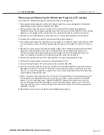
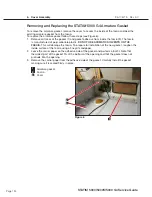
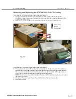
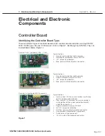
To remove the fascia, follow these steps (see Figure 8):
1. Place it right side up on a worksurface and remove the LCD overlay and the colour LCD
touchscreen (see Removing LCD overlay and removing Colour LCD touchscreen)
2. Turn the cover upside down and remove the colour LCD controller board, speaker,
Ethernet port and USB port (See removing LCD controller board, speaker, Ethernet port
and USB port).
3. The fascia is attached to the cover (1) using seven plastite screws (2). Remove and
retain the screws.
4. A bead of silicone was used to provide a water-tight seal between the fascia and cover
during manufacturing. Remove the fascia and any silicon residue remaining on the cover.
5. Discard the old fascia. The fascia is made of recyclable polycarbonate. Please recycle
wherever possible.
To replace the fascia, follow these steps (see Figure 8):
1. Apply a bead of silicon between the fascia and cover (1) to provide a water-tight seal.
2. Install the new fascia using the seven screws (2) retained from the disassembly
procedure.
3. Reinstall the colour LCD touchscreen and LCD overlay.
4. Turn it upside down and reinstall the colour LCD controller board, speaker, USB and
Ethernet ports.
5. Reinstall the cover.
6. Verify that the colour LCD functions correctly.
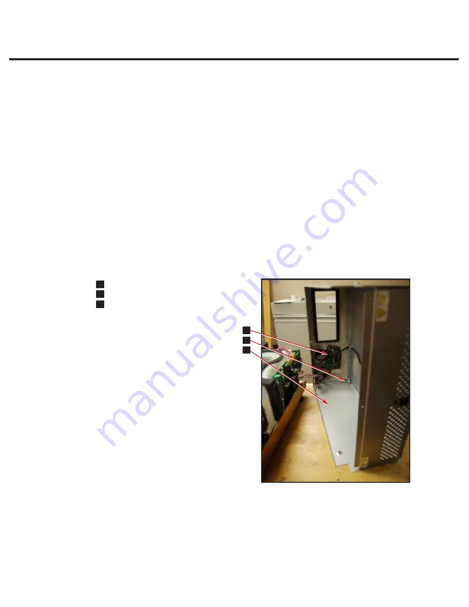
Cover Assembly
n
1
Cover
n
3
Plastite screws
n
3
LCD controller board
1
2
3
Figure 8
3
2
1
STAT
IM
5000/5000S/5000 G4 Service Guide
Removing and Replacing the STAT
IM 5000 G4 Fascia
To remove the fascia, follow these steps (see Figure 9):
1. Place it right side up on a worksurface and remove the LCD overlay and the colour LCD
touchscreen (see Removing LCD overlay and removing Colour LCD touchscreen)
2. Turn the cover upside down and remove the colour LCD controller board, speaker, Ethernet
port and USB port (See removing LCD controller board, speaker, Ethernet port and USB port).
3. The fascia is attached to the cover (1) using seven plastite screws (2). Remove and retain the
screws.
4. A bead of silicone was used to provide a water-tight seal between the fascia and cover during
manufacturing. Remove the fascia and any silicon residue remaining on the cover.
5. Discard the old fascia. The fascia is made of recyclable polycarbonate. Please recycle
wherever possible.
To replace the fascia, follow these steps (see Figure 8):
1. Apply a bead of silicon between the fascia and cover (1) to provide a water-tight seal.
2. Install the new fascia using the seven screws (2) retained from the disassembly procedure.
3. Reinstall the colour LCD touchscreen and LCD overlay.
4. Turn it upside down and reinstall the colour LCD controller board, speaker, USB and
Ethernet ports.
5. Reinstall the cover.
6. Verify that the colour LCD functions correctly.
Figure 9


