Page 15
STAT
IM 2000/2000S
Service Guide
96-106775 Rev 5.0
2. Tools, Maintenance Schedules, Procedures and Testing
STAT
IM
5000/5000S/5000 G4 Service Guide
The Control Box
NoTe:
late model STAT
IMs with
Rev.7 boards can be calibrated with the
cover on using the unit’s software and
keypad, making use of the Control Box
as an option. For older models, use of a
control box is required.
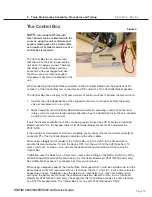
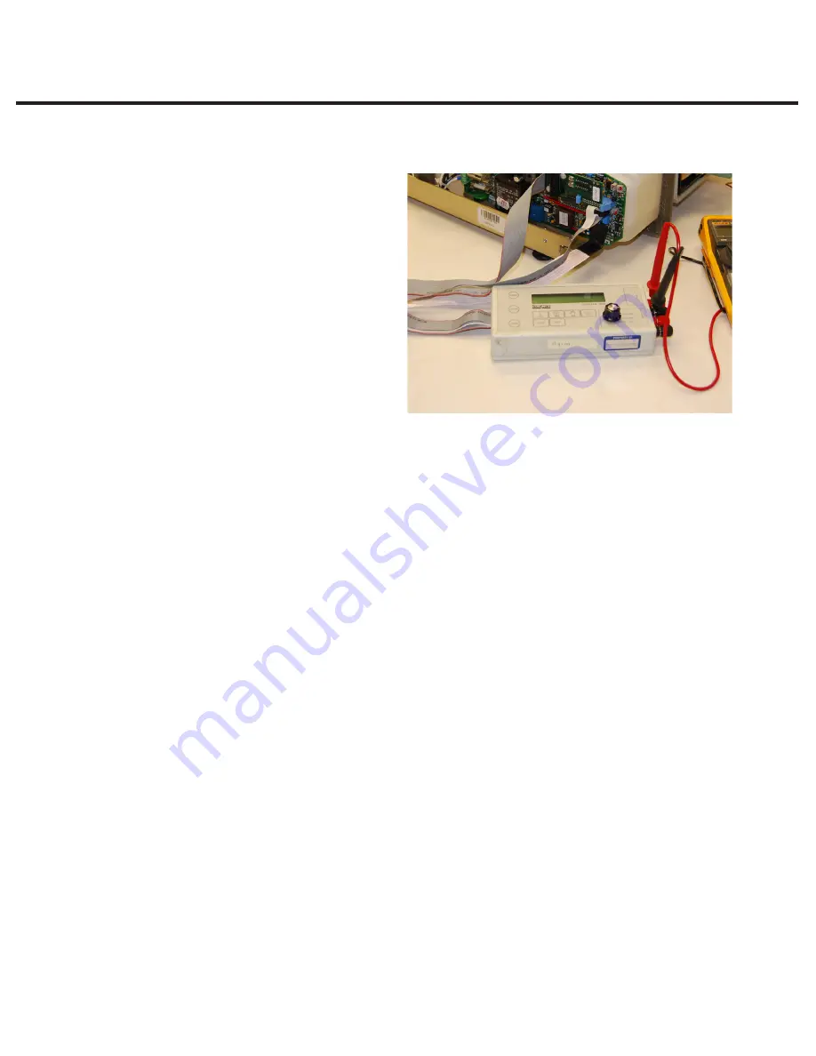
The Control Box (5) is a service tool
that allows a technician to operate the
unit while it is being serviced. There are
two kinds of Control Boxes you may
encounter: one uses toggle switches,
the other uses a membrane keypad
arrangement similar to the keypad on the
unit.
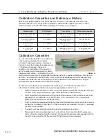
When connecting the Control Box connectors to the Controller Board note the positions of Pin
number 1 of the Control Box test connectors and Pin number 1 of the Controller Board headers.
The Control Box has a display (LCD) and a variety of control switches that allow the technician to:
1. Operate the unit independently of the keypad mechanism, to manually activate the pump,
valve or compressor, or run cycles.
2. Make frequently used Controller Board measurements by providing a common output and
rotary switch for signal selection during calibration. See the Calibration Instructions in chapters
4 and 5 of this service manual.
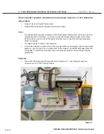
If only the display and button functions are being used, connect the LCD cable (6) to Controller
Board connector P3, the keypad cable (7) to Controller Board connector P4 and power the
STAT
IM ON.
If the override or measurement functions are being used, connect the test connector cable (8) to
connector P1 of the Controller Board in addition to the other cables.
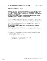
When using a toggle switch model of the Control Box, turn the switch to the ON position to
activate the desired device. To turn the device OFF, turn the switch to the AUTO position. To
select, start and / or stop a cycle, activate the appropriate push-button switch on top of the
Control Box.
Calibration uses the Select out +, Select out - jacks and a setting on the Rotary Switch to set the
calibration operation desired for Revision 3.x/4.x Controller Boards (for STAT
im
2000 units only).
See Calibration Procedure 1 or chapter 4 of this service manual.
When using a keypad model of the Control Box, the keypad switch must be held down to turn the
desired device ON. Vref measurements use test leads, the Vref + and Vref - jacks and a voltmeter
hooked up in series. Calibration uses the Select out + and Select out - jacks, test leads and a
setting on the Rotary Switch to set the calibration operation desired for Rev. 3.x/4.x Controller
Boards (for STAT
im
2000 units only). The keypad of this Control Box provides the same features
as a STAT
IM keypad. Note: The Control Box is for use with STATIM products ONLY.
Figure 3


