Page 152
STAT
IM 2000/2000S
Service Guide
96-106775 Rev 5.0
7. Electrical and Electronic Components
Microswitch
The function of the microswitch is to sense the presence of the cassette when it is inserted in the
armature. When the cassette activates the switch, it is possible to start the unit. With the cassette
out, the unit will not start.
Failure of the switch will produce the following symptoms:
• Failed ‘ON’ — the unit may start WITHOUT the cassette being engaged.
• Failed ‘OFF’ — the unit will not start even with the cassette fully engaged.
Removing the Microswitch
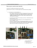
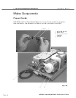
To remove the microswitch, proceed as follows (see Figure 19):
1. Turn the power switch OFF, and unplug the unit.
2. Disconnect the microswitch leads (1) from the controller board (2) terminal block positions
labelled CASSIN J4-1 AND J4-2 (J3-1 and J3-2 on Rev. 3.0 boards) and carefully cut the cable
ties securing the microswitch leads to the wiring harness.
3. There may be RTV silicone sealant on the heads of the two screws (3) securing the
microswitch (4) to the side of the probe bracket (5). Trim away the excess RTV silicone and
remove the screws. Retain these for assembling the replacement microswitch to the probe
bracket.
4. Remove the microswitch.
5. Remove all RTV silicone residues from the probe bracket surface.
STAT
IM
5000/5000S/5000 G4 Service Guide
1. Microswitch leads
2. Controller Board
3. Screws
4. Microswitch
5. Probe bracket
Figure 19

