Page 165
STAT
IM 2000/2000S
Service Guide
96-106775 Rev 5.0
8. Water Pumps, Reservoir, and Compressor
STAT
IM
5000/5000S/5000 G4 Service Guide
Performing internal pump filter maintenance
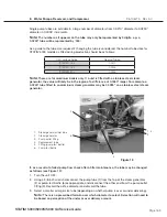
For filter maintenance on internal filters located in the pump, proceed as follows (see Figure 6):
Tip: This can be undertaken with the pump in place, but it is easier if the pump is removed
from the unit.
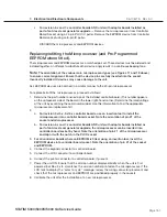
1. Drain the reservoir (1). See, Tools, Maintenance Schedules, Procedures and Testing.
2. Remove the four screws with washers (2) securing the compressor / bracket assembly (3). See,
Compressor.
3. If the pressure transducer (4) is present disconnect the transducer connector (5). See
PressureTransducer.
4. Remove the compression nut (6) holding the compressor output tube (7) to the compressor and
disconnect the tube.
5. Rest the compressor / bracket assembly to one side to access the pump.
1. reservoir
2. screws with washers
3. compressor / bracket
assembly
4. pressure transducer
5. transducer connector
6. compressor compression nut
7. compressor output tube
8. cable tie
9. pump inlet tube
10. pump inlet fitting,
11. Teflon™ tube
12. right angle pump outlet fitting
13. pump body fitting
14. mesh filter, integral to item 10
15. rubber seal, integral to item 10
16. pump
17. pump body outlet fitting
(same as 12)
18. steam generator
19. insert with mesh filter,
integral to item 6
Figure 6

