Page 202
STAT
IM 2000/2000S
Service Guide
96-106775 Rev 5.0
9. Solenoid Valve and Pressure Transducer
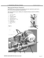
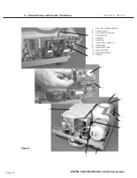
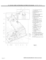
To remove the pressure transducer (1), proceed as follows (see Figure 6):
1. Turn the power switch (2)
oFF
, and unplug the mains power cable (3) (not shown). Allow time
for the unit to cool.
2. Disconnect the transducer connector (4) from the top of the transducer.
3. Using a 3/8-inch wrench, disconnect the compression nut (8) holding the coiled transducer
tube (6), from the bottom of the transducer.
4. Using a 7/8-inch wrench or an adjustable wrench, remove the transducer nut and washer (9)
securing the transducer to the bracket (10).
5. Should removal of the transducer bracket be necessary, remove the screw and washer (11)
holding the bracket to the chassis (12).
6. If the transducer is damaged, discard the transducer.
Reinstalling the Pressure Transducer
To reinstall the pressure transducer (1), proceed as follows (see Figure 6):
1. Make sure the power switch (2) is
oFF
, and the unit is unplugged.
2. If the transducer bracket (10) was removed, reinstall the bracket on the chassis (12) using the
screw and washer (11) retained from disassembly.
3. Install the transducer in the transducer bracket using the nut and washer (9) retained from
disassembly. Tighten with a 7/8-inch wrench or an adjustable wrench.
4. Reconnect the transducer tube (6) to the bottom of the transducer. Thread the compression
nut (8) finger tight, and then tighten the compression nut using a 3/8-inch wrench.
Do not over
tighten
.
5. If the transducer tube has been removed completely or is being replaced, reconnect the
other end of the coiled transducer tube to the solenoid valve inlet “T” fitting (7). Thread the
compression nut (5) finger tight, and then tighten the compression nut using a 3/8-inch
wrench.
Do not over tighten
.
6. Hold the transducer / bracket assembly with one hand and plug the transducer connector (4)
onto the transducer. Make sure the tab on the connector snaps in place.
7. Check that all fittings have been tightened and that all brackets are secured to the chassis.
Reconnect the mains electrical cable (3) (not shown) and turn the power switch (2)
oN
.
8. Run a sterilization cycle and observe all fittings and tubes for leaks. Check LCD read-out for
messages indicating cycle status.
Important note:
the pressure transducer performs a critical process monitoring function
during the sterilization cycle and must be recalibrated prior to the unit being used to process
instruments. Refer to the relevent calibration procedure and re-calibrate the unit upon
completion of the repair.
STAT
IM
5000/5000S/5000 G4 Service Guide


