Page 225
STAT
IM 2000/2000S
Service Guide
96-106775 Rev 5.0
11. Steam Generator, Check Valve, Thermal Fuse and Pressure Relief Valve
STAT
IM
5000/5000S/5000 G4 Service Guide
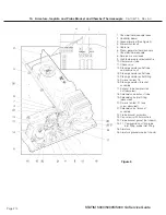
5. Connect the compression nut (16) holding the Teflon™ tube (17) to the top of the steam
generator. Thread the nut finger tight, then tighten. Do not over tighten.
6. Reconnect the white wire (12) to the terminal on the lower half of the steam generator using
the retained screw with lockwasher. Tip: If the terminal appears blackened, clean it using fine
grit sandpaper. If the terminal threads are stripped, use a nut on the other side of the terminal
to hold the screw.
7. Route the black thermal fuse wire (4) from the fuse assembly along the back of the chassis
along the wiring harness, and connect it to controller board. Re-secure the harness with cable
ties.
8. Check the bend and route of the steam generator thermocouple lead (8) and place alongside
the chamber thermocouple lead to the controller board. The leads must not touch the cover
when the cover is assembled to the chassis.
9. Reconnect the ground lead terminal (3) to the position marked BOILER directly above the
thermocouple terminals on the controller board.
10.
a.
For all controller boards other than revision 7.x.
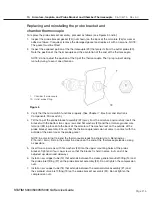
Check the pre-bend on both
thermocouple leads to ensure that they are the required shape to go under the washers on
the connections without touching anything other than the terminal.
CAuTIoN:
The thermocouple leads at the board end are very fragile.
The unmarked lead is positive, +Y, and red lead is negative, -R. Connect the unmarked
lead to the terminal Y on the controller board. Connect the red lead to the
terminal marked -R on the controller board. Make sure there is extra lead length so that
the wires do not break as the screw is tightened. Ensure that the wires are seated securely
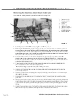
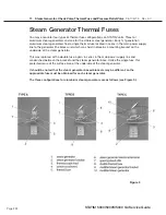
behind the respective washers (see Figure 1 detail).
The two leads must not touch one another or any other component. Do not calibrate a
thermocouple until it is properly installed and positioned in the unit.
b.
For revision 7.x controller boards.
Reconnect the chamber thermocouple plug to the
socket on the controller board (See Figure 1 detail).
11. Bundle the chamber thermocouple lead (7), the steam generator thermocouple lead, the
validation thermocouple lead (where fitted), pressure transducer leads (where fitted),
micro switch leads (9) and reservoir sensor leads (10) together using nylon cable ties (6),
approximately every 2-3 inches. Secure the wires to the top of the armature using the cable
anchors provided.
12. Carefully push the compressor tube (14) (where a compressor is fitted) onto the check valve
inlet (15) and secure the tube to the valve using a high temperature rated cable tie (13).
13. Replace the pressure interface board or printer cable (if fitted) into the blue socket.
14. A dielectric strength test (Hi-Pot) and a protective bonding impedance test (ground continuity)
should be performed on the STAT
im
unit at this stage.
NOTE:
These tests must be performed on the STAT
im
again once the work is completed and
the cover has been returned to the unit.
15. Refill the reservoir using steam process distilled water.
16. Recalibrate the unit as appropriate.
17. Run a sterilization cycle and observe all fittings and tubes for leaks. Check LCD read-outs for
messages indicating cycle status.
18. Reinstall the cover.


