Page 229
STAT
IM 2000/2000S
Service Guide
96-106775 Rev 5.0
11. Steam Generator, Check Valve, Thermal Fuse and Pressure Relief Valve
STAT
IM
5000/5000S/5000 G4 Service Guide
14. A dielectric strength test (Hi-Pot) and a protective bonding impedance test (ground continuity)
should be performed on the STAT
im
unit at this stage.
NOTE:
These tests must be performed on the STAT
im
again once the work is completed and
the cover has been returned to the unit.
15. Refill the reservoir using steam process distilled water.
16. Recalibrate the unit as appropriate.
17. Run a sterilization cycle and observe all fittings and tubes for leaks. Check LCD read-outs for
messages indicating cycle status.
18. Reinstall the cover.
Check valves
The check valve on STAT
IM units is basically a non return valve that allows air from the
compressor to pass through the steam generator, into the chamber (cassette) to dry the
instruments, and exhaust through the solenoid valve to the waste bottle after the unit has vented.
It should not allow steam to pass back through the valve and into the compressor. Failure can lead
to a drop in pressure in the unit during processing and cause damage to the compressor. Note:
As a critical component it is recommended that the check valve is changed annually as part of a
routine service.
CAuTIoN:
The steam generator and check valve may be hot. Guard against burns.
The steam generator check valve is found on STAT
IM 5000 and 5000S units with compressors.
Testing the Check valve
There are two options of checking the check valve, either with the unit running or manually with
the control box.
option 1: Checking the valve with the unit running.
To perform this test, the STAT
im
unit must be running with the cover off and the control box
attached as if running as test cycle during servicing. For revision 7.x units, the unit can be run with
the cover removed but still connected to the controller.
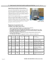
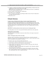
To inspect the check valve, proceed as follows (See Figure 8):
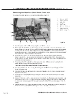
1. Carefully pull the compressor tube (2) from the check valve barb fitting.
2. Start a normal cycle on the unit and wait for the unit to pressurise.
3. Using a reflective, cold surface (e.g. a dental mirror), place it close to the check valve inlet
fitting and observe for condensation.
4. If condensation is apparent, manually inspect the compressor air filter, the bacteria retentive
filter (if present) and the compressor.
5. If there is evidence of water in the bacteria retentive filter, replace the check valve and the
filter. If there is evidence of water in the compressor or if the compressor filter is wet, replace
the steam generator check valve, compressor and filters.

