Page 234
STAT
IM 2000/2000S
Service Guide
96-106775 Rev 5.0
11. Steam Generator, Check Valve, Thermal Fuse and Pressure Relief Valve
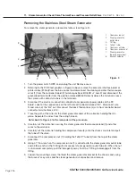
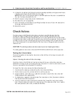
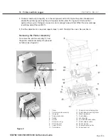
6. Remove the two screws (14) from the steam generator bracket (15). Note: The steam generator
will still be attached to the PCB by the thermocouple lead (16).
7. Carefully cut the two cable ties closest to the steam generator that hold the thermocouple
leads together.
8. Gently lift and turn the steam generator assembly onto one side to expose the bottom of the
assembly. Be careful not to stress the thermocouple leads. (Min. bend radius - 3/16 inch / 5 mm).
9. Remove the small screw (17) that attaches the steam generator bracket to the steam generator.
10. Disconnect the thermal fuse (18) from the lower power terminal on the steam generator. Note
the routing of the thermal fuse assembly between the bracket and spacing lugs (20) on the
bottom of the steam generator.
11. Remove the thermal fuse.
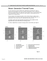
1. high temperature
rated cable tie
2. compressor tube
3. check valve inlet
4. black thermal fuse wire
5. aluminum steam generator
6. white wire (attaches here)
7. compression nut
8. Teflon™ tube
9. compression nut
10. steam generator outlet tube
11. probe bracket inlet fitting
12. compression nut
13. steam generator outlet fitting
14. two screws (obscured)
15. steam generator bracket
16. thermocouple lead
17. screw
18. thermal fuse
19. steam generator electrical
terminal
20. spacing stand-offs
21. double thermal fuse
22. modified steam generator
bracket
23. modified steam generator
STAT
IM
5000/5000S/5000 G4 Service Guide
Figure 11


