Page 87
STAT
IM 2000/2000S
Service Guide
96-106775 Rev 5.0
4. STAT
IM 5000 Calibration
STAT
IM
5000/5000S/5000 G4 Service Guide
1.
Reference voltage verification / adjustment
To verify / adjust the reference voltage:
• Ensure the unit is
oFF.
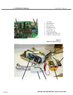
• Connect the control cox (1) to the controller board (2).
• Connect the digital voltmeter (4) to the Vref terminals on the control box.
• Set the voltmeter to read DC Volts with a resolution of 1mV.
• Power the unit
oN
.
• Adjust the Vref potentiometer until Vref is 2.520 V ± 0.001.
• Once Vref is adjusted, apply a drop of non-conducting lacquer or nail polish to the
adjustment screw of the potentiometer.
2.
Chamber thermocouple calibration
To calibrate the chamber thermocouple:
• Turn the power switch to
oFF
. Ensure the calibration jumper is in place and turn the power
switch
oN
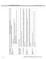
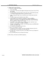
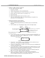
. The LCD will read (for example):
• To start a chamber calibration cycle,
press and release
the UNWRAPPED cycle button
on the control box and then press the
START
button. The STAT
IM will run a regular
UNWRAPPED cycle, but continue to show calibration information on the LCD.
• Wait for the chamber to reach the sterilization temperature of 134 °C (TTT).
• The temperature displayed on the LCD needs to match the temperature displayed on the
digital thermometer.
• To change the temperature display on the LCD, adjust the TC-ADJ potentiometer (9) on
the controller board. Continue adjusting TC-ADJ until the temperatures are within ±0.2°C.
• Observe the temperatures displayed on the LCD and the digital thermometer for 30
seconds. The temperatures registered should remain within ± 0.2°C of one another. Adjust
TC-ADJ if not.
• Press the
SToP
button on the control box when finished.
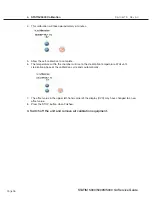
VVV
TTT
DDD
TO
CVO
Validation Thermocouple
hexadecimal offset
compared
with chamber reading
Validation
Thermocouple
reading
Difference between
Validation TC and chamber
temperatures in °C
Chamber
Thermocouple
hexadecimal offset
Chamber
Thermocouple in °C


