AVS-01
A
UDIO
/V
IDEO
S
ELECTOR
December 14, 2001
VERSION 1.0
2
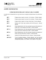
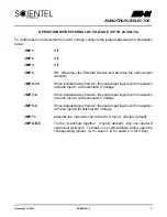
JUMPER CONFIGURATION
OPERATION WITH EXTERNAL DRY CONTACTS (RELAY CLOSUR
E)
To control each or all selectors from a dry contact closure, configure the jumpers based on the information
below:
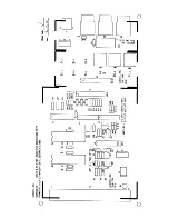
JMP 1
Enables pull-up resistor on Audio 1 Control Input. (Factory default)
JMP 2
Enables pull-up resistor on Audio 2 Control Input. (Factory default)
JMP 3
Enables pull-up resistor on Video Control Input. (Factory default)
JMP 4
Attaches the Control Input common with the DC ground. (Factory
default)
JMP 9-10
When installed close to U2, they set proper logic level for operation of
Audio input 1 with external dry contacts. (Factory default)
JMP 7-8
When installed close to U2, they set proper logic level for operation of
Audio input 2 with external dry contacts. (Factory default)
JMP 5-6
When installed close to U2, they set proper logic level for operation of
Video input with external dry contacts. (Factory default)
JMP 11
Attaches the Video ground to the DC Ground. (Factory default)
JMP A,B,C
Tie the 3 switchers together. (Factory default). Any one input will
operate all switchers. To break one or all switchers simply open the
corresponding jumper. (A for Audio 1, B for audio 2, C for Video)
Summary of Contents for AVS-01
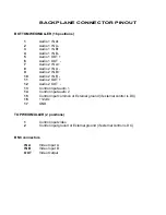
Page 6: ...APPENDIX A BACKPLANE CONNECTOR PINOUT ...
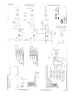
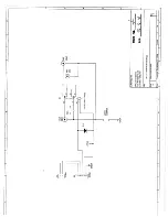
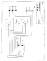
Page 8: ...APPENDIX B SCHEMATIC LAYOUT DIAGRAMS ...
Page 9: ......
Page 10: ......
Page 11: ......
Page 12: ......


