Functional Description
Functional Description
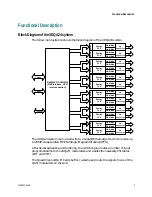
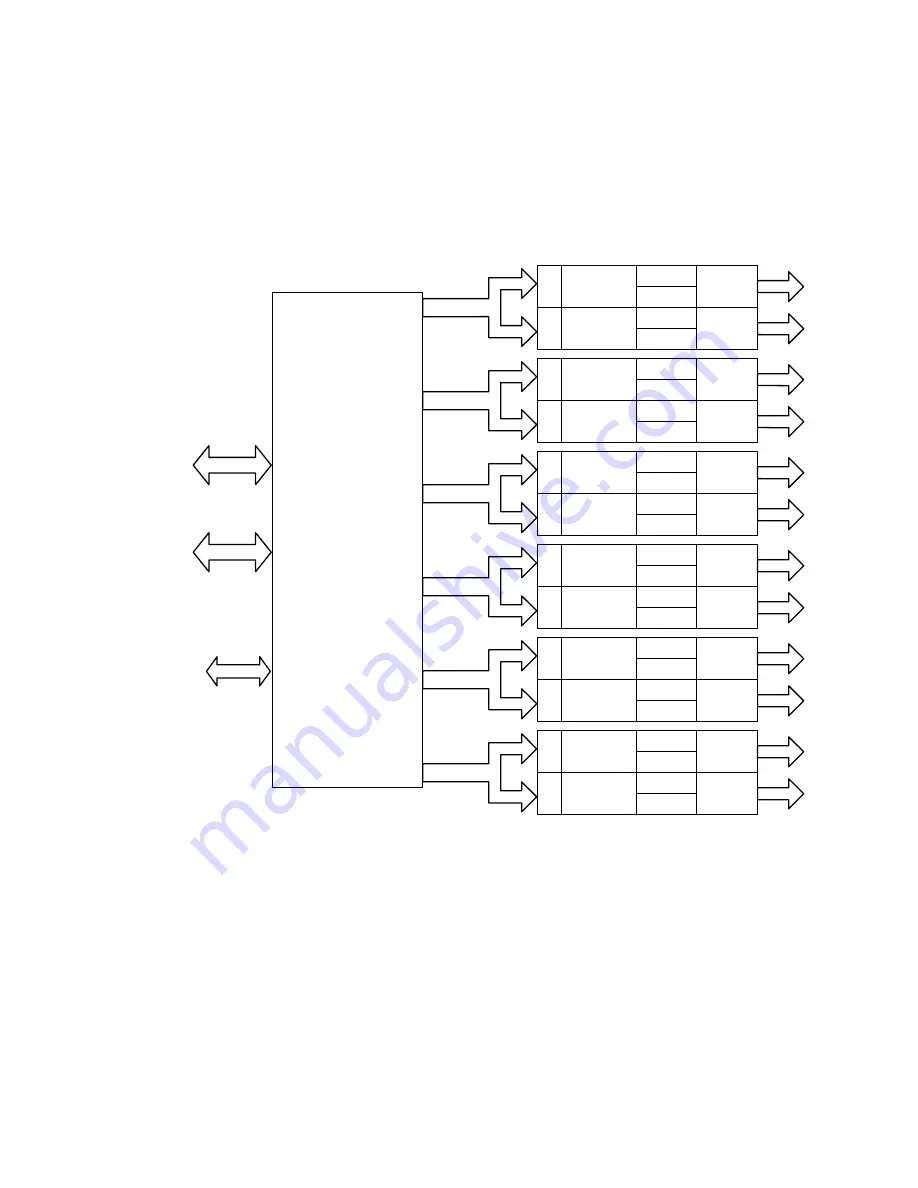
Block Diagram of the XDQA24 system
The following illustration shows the block diagram of the XDQA24 system.
1 Gbps
System Controller
(GbE interface, CPU,
interconnection)
1 Gbps
10/100BT
RF
Buff
er
Routing
PCR
QAM Mod
QAM Mod
Up
converter
Bu
ff
e
r
Routing
PCR
QAM Mod
QAM Mod
Up
converter
RF
RF
Bu
ff
er
Routing
PCR
QAM Mod
QAM Mod
Up
converter
Bu
ff
er
Routing
PCR
QAM Mod
QAM Mod
Up
converter
RF
RF
Buffe
r
Routing
PCR
QAM Mod
QAM Mod
Up
converter
Buffe
r
Routing
PCR
QAM Mod
QAM Mod
Up
converter
RF
RF
Bu
ff
e
r
Routing
PCR
QAM Mod
QAM Mod
Up
converter
Buffe
r
Routing
PCR
QAM Mod
QAM Mod
Up
converter
RF
RF
Bu
ff
er
Routing
PCR
QAM Mod
Bu
ff
e
r
Routing
PCR
QAM Mod
QAM Mod
Up
converter
RF
QAM Mod
Up
converter
RF
Buffe
r
Routing
PCR
QAM Mod
B
u
ffe
r
Routing
PCR
QAM Mod
QAM Mod
Up
converter
QAM Mod
Up
converter
RF
The XDQA24 system is provided with two Gigabit Ethernet ports, which receive up
to 256 IP-encapsulated MPEG2 Single Program Streams (SPTS).
After de-encapsulating and buffering, the switch engine routes a number of input
program streams to the 24 QAM modulators and creates the necessary PSI tables
(PAT and PMT).
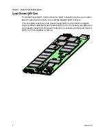
The Quad Channel QAM Cards buffer, re-stamp and route the signals to one of the
QAM modulators on the card.
4018055 Rev B
3
Summary of Contents for Continuum DVP eXtra Dense QAM Array 24
Page 1: ...4018055 Rev B Continuum DVP eXtra Dense QAM Array 24 Configuration Guide...
Page 2: ......
Page 4: ...For Your Safety iv 4018055 Rev B...
Page 6: ......
Page 10: ......
Page 12: ......
Page 14: ......
Page 24: ......
Page 32: ......
Page 44: ...Chapter 3 Configuring the XDQA24 System 30 4018055 Rev B...
Page 64: ......
Page 88: ......
Page 96: ......
Page 103: ......

