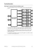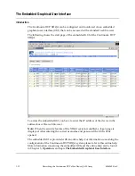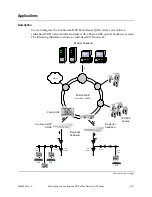
Continuum DVP eXtra Dense QAM Array Housing,
Continued
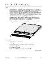
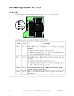
LED Indicators
The following table describes the LED indicators on the front panel.
Label Type
Description
Red
Indicates a pending alarm or error detected
by the processor.
ALARM
Green Status
OK
Red
The main power supply is inactive.
Green
Illuminates if the main power supply is
active.
MAIN
Extinguished
No main power supply is available.
Red
The backup power supply is inactive.
Green
Illuminates if the backup power supply is
active.
BACKUP
Extinguished
No backup power supply is available.
Connectors
The following table describes the connectors on the rear panel.
Label Type
Description
RF OUT 1 - 6
F
RF output
GbE 1-2
RJ-45 (electrical)
SFP (optical)
IP input
Ethernet 10BT
RJ-45
10Base-T Ethernet port to set the IP address
of both ports and to manage the device
Ethernet
10/100BT
RJ-45
10/100Base-T Ethernet port to manage the
device
Additional Information
For more information about the Continuum DVP eXtra Dense QAM Array housing
specifications, see Appendix A,
Technical Specifications
.
1-6
Describing the Continuum DVP eXtra Dense QAM Array
4004949 Rev C
Summary of Contents for Continuum DVP eXtra Dense QAM Array
Page 1: ...Continuum DVP eXtra Dense QAM Array System Guide...
Page 3: ...Continuum DVP eXtra Dense QAM Array System Guide...
Page 18: ...xvi 4004949 Rev C...
Page 20: ......
Page 36: ......
Page 38: ...2 2 Installation 4004949 Rev C...
Page 68: ......
Page 80: ......
Page 86: ......
Page 88: ......
Page 94: ......
Page 100: ......
Page 106: ......
Page 110: ......
Page 111: ......

