background image

Functional Description 

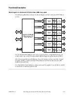
Block Diagram of a Continuum DVP eXtra Dense QAM Array system 

The following illustration shows the block diagram of the Continuum DVP XDQA 
system. 

102 Mbps

RF

Buff

er

Routing

PCR

QAM
Mod

QAM
Mod

Up

converter

1 Gbps

System Controller

(GbE interface, CPU,

interconnection)

1 Gbps

102 Mbps

RF

B

u

ffe

r

Routing

PCR

QAM
Mod

QAM
Mod

Up

converter

102 Mbps

RF

B

u

ffe

r

Routing

PCR

QAM
Mod

QAM
Mod

Up

converter

102 Mbps

RF

Buff

er

Routing

PCR

QAM
Mod

QAM
Mod

Up

converter

102 Mbps

RF

Buff

er

Routing

PCR

QAM
Mod

QAM
Mod

Up

converter

102 Mbps

RF

Buff

er

Routing

PCR

QAM
Mod

QAM
Mod

Up

converter

10/100BT


The Continuum DVP XDQA system is provided with two Gigabit Ethernet ports, 
which receive up to 512 IP-encapsulated MPEG2 Single Program Streams (SPTS) 

After de-encapsulating and buffering, the switch engine routes a number of input 
program streams to the sixteen QAM modulators and creates the necessary PSI 
tables (PAT and PMT). 

The Dual QAM Cards buffer, re-stamp and route the signals to one of the two QAM 
modulators on the Dual QAM Cards. 


4004949 Rev C 

Describing the Continuum DVP eXtra Dense QAM Array 

1-11 

Summary of Contents for Continuum DVP eXtra Dense QAM Array

Page 1: ...Continuum DVP eXtra Dense QAM Array System Guide...

Page 2: ...the flash points to the terminal device You may find this symbol affixed to the product This symbol indicates a protective ground terminal You may find this symbol affixed to the product This symbol...

Page 3: ...Continuum DVP eXtra Dense QAM Array System Guide...

Page 4: ...formation in this document employs an invention claimed in any existing or later issued patent Copyright 2005 Scientific Atlanta Europe NV All rights reserved Printed in Mexico Information in this pub...

Page 5: ...Section A Installing the Continuum DVP eXtra Dense QAM Array Housing Overview 2 3 Preparing for Installation 2 4 Rack Mounting the Continuum DVP eXtra Dense QAM Array Housing 2 5 Section B Installing...

Page 6: ...Maintenance and Troubleshooting Overview 4 1 Maintenance 4 2 Troubleshooting 4 4 Chapter 5 Customer Information Overview 5 1 Product Support 5 2 Return Products for Repair 5 4 Appendix A Technical Sp...

Page 7: ...interpreted as having the same meaning as earth ing Electric Shock Hazard This equipment meets applicable safety standards Refer to this equipment s data sheet for details about regulatory compliance...

Page 8: ...urces such as radiators heat registers stoves or other equipment including amplifiers that produce heat Place this equipment close enough to a mains AC outlet to accommodate the length of this equipme...

Page 9: ...airflow required for safe operation of this equipment is not compromised Elevated Operating Ambient Temperature Only install this equipment in a humidity and temperature controlled environment that me...

Page 10: ...let in which one socket is wider than the other Note If this plug cannot be fully inserted into the outlet try reversing the plug If the plug still fails to fit contact an electrician to replace the o...

Page 11: ...to 48 V DC 60 V DC Power Sources If this equipment is DC powered refer to this equipment s specific installation instructions in this manual or in companion manuals in this series for connection to n...

Page 12: ...ent and perform safety checks to ensure it is safe to use before putting it back into operation Electrostatic Discharge Electrostatic discharge ESD results from the static electricity buildup on the h...

Page 13: ...compatibility EMC regulatory requirements Refer to this equipment s data sheet for details about regulatory compliance approvals EMC performance is dependent upon the use of correctly shielded cables...

Page 14: ...ences du R glement sur le mat riel brouilleur du Canada CENELEC CISPR Statement with Respect to Class A Information Technology Equipment This is a Class A equipment In a domestic environment this equi...

Page 15: ...itted from an unterminated fiber Do not view an activated fiber with optical instruments e g eye loupes magnifiers microscopes Use safety approved optical fiber cable to maintain compliance with appli...

Page 16: ...abel that clearly indicates the laser aperture is affixed to the equipment s rear panel The following illustration displays the location of the laser label on the equipment s rear panel FAN 3 10bT 10...

Page 17: ...ra Dense QAM Array system are classified in class 1 laser products according to IEC 60825 1 1997 amendment 2001 The label below is attached to the top cover and the package of class 1 laser product CL...

Page 18: ...xvi 4004949 Rev C...

Page 19: ...personnel refer to the safety guidelines and precautions earlier in this manual Related Publications Refer to the following Scientific Atlanta publications for more information Reference Note Continuu...

Page 20: ......

Page 21: ...pter This chapter contains the following topics Topic See Page Continuum DVP eXtra Dense QAM Array System 1 2 Continuum DVP eXtra Dense QAM Array Housing 1 5 Continuum DVP eXtra Dense QAM Array Power...

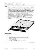
Page 22: ...s two adjacent RF output channels The compact modular design allows you to customize your VOD application for up to 188 VOD streams 3 Mbps 8Mhz 256 QAM according to your specific needs The following i...

Page 23: ...r concept ensures easy system capacity upgrades The following illustration is a view of a Continuum DVP XDQA system Continuum DVP eXtra Dense QAM Array Alarm Main Backup The following Continuum DVP XD...

Page 24: ...only Compliant with Motorola Pre Scrambling Hot swappable auto configurable QAM cards containing two QAM channels on a single RF connector 2 Redundant GbE Inputs for interfacing with VOD Servers Easy...

Page 25: ...tical GbE ports can be configured with SFP type laser module The fans mounted at the back of the device and in the PSU modules create an optimal airflow inside the housing by which the Continuum DVP X...

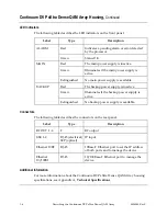
Page 26: ...he backup power supply is active BACKUP Extinguished No backup power supply is available Connectors The following table describes the connectors on the rear panel Label Type Description RF OUT 1 6 F R...

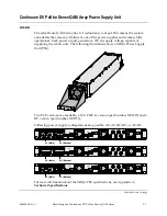
Page 27: ...100 240V ac version part number 1001815 and a DC version part number 1001773 Following power supply configurations are possible AC AC DC DC or AC DC FAN 1 FAN 2 FAN 3 GbE 1 GbE 2 10 100bT 10bT 1 4 2 3...

Page 28: ...haring based on droop method Power Factor Corrected EN 61000 3 2 compliant 1 isolated fully protected 12V DC output Features and Benefits of the DC Version PSU The standard features and benefits are U...

Page 29: ...rmation about the Dense QAM Array Dual QAM Card specifications see Appendix A Technical Specifications Features and Benefits The standard features and benefits are New DirectRF technology significantl...

Page 30: ...ng indicate data traffic on the channel higher than 1 16 of the full data rate playout CH1 Green This LED indicates data traffic on channel 1 upper frequency channel Illuminated faintly the card is po...

Page 31: ...QAM Mod Up converter 102 Mbps RF Buffer Routing PCR QAM Mod QAM Mod Up converter 102 Mbps RF Buffer Routing PCR QAM Mod QAM Mod Up converter 10 100BT The Continuum DVP XDQA system is provided with two...

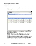
Page 32: ...ress box of the web browser Note When the security feature of the XDQA system is enabled a logon page is displayed After entering the correct username and password the GUI will be opened The embedded...

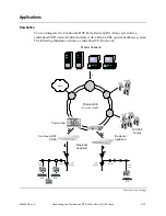
Page 33: ...entralized VOD network IP IP over SDH SONET Prisma GbE 100 000 homes WWW VOD server VOD server Billing system Resource manager Master headend Regional headend TAP Line amplifier Trunk amplifier Drop c...

Page 34: ...IP addresses table After confirmation of the billing system and resource manager the server sends a confirmation message to the STB The STB sends back a request for playing the movie In the same way t...

Page 35: ...available on the label s Company address Model number Serial number Part number Nominal supply voltage Maximum current Under some circumstances you might need this information For example when a unit...

Page 36: ......

Page 37: ...all operate or maintain the Continuum DVP XDQA system CAUTION Allow only qualified personnel to maintain and service this product Otherwise personal injury or equipment damage may occur In This Chapte...

Page 38: ...2 2 Installation 4004949 Rev C...

Page 39: ...n explains how to install the Continuum DVP eXtra Dense QAM Array Housing in a standard 19 inch rack In This Section This section contains the following topics Topic See Page Preparing for Installatio...

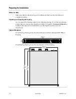
Page 40: ...customer services department Refer to Chapter 5 Customer Information further in this manual for information on contacting the customer services department Chassis Dimensions The following drawing show...

Page 41: ...is CAUTION It is of great importance to place the Continuum DVP XDQA Housing and its components in a conditioned room within the ambient temperature specifications For more information see Appendix A...

Page 42: ...Scientific Atlanta 1 2 3 4 5 6 7 8 GbE Scientific Atlanta 1 2 3 4 5 6 7 8 GbE Scientific Atlanta 1 2 3 4 5 6 7 8 1 2 3 4 5 6 1 2 3 4 5 6 Scientific Atlanta 1 2 2 1 4 3 6 5 8 7 10 9 12 11 14 13 16 15 1...

Page 43: ...have been followed prior to performing the installation procedures in this chapter It is recommended that the entire installation procedure in this chapter is read prior to perform the installation In...

Page 44: ...lide evenly into the slot Modules contain static sensitive devices Always follow proper electrostatic discharge ESD handling procedures wristband with ground strap and ESD mat when installing modules...

Page 45: ...rform the following procedure to install the PSU into the chassis 1 Unpack the PSU CAUTION Follow proper ESD handling procedures ESD may cause permanent damage to electronic components When unpacking...

Page 46: ...the housing and tighten these screws To Remove a PSU When you have read the Important Safety Instructions earlier in this guide you are ready to remove the PSU from the housing Perform the following s...

Page 47: ...AM Card When you have read the Important Safety Instructions earlier in this guide you are ready to install the Dual QAM Card in the Continuum DVP XDQA Housing Perform the following procedure to insta...

Page 48: ...slot 4 Push the card carefully into the system controller connector 5 Connect the cable with the connector nearest the board connector to the Dual QAM Card 6 Position the front cover on the housing p...

Page 49: ...of the housing and remove the front cover 2 Disconnect the cable from the connector on the Dual QAM Card WARNING Pulling out the Card without disconnecting the cable may cause in permanent damage of t...

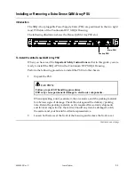
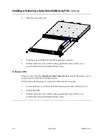
Page 50: ...es detail a in the illustration below The Button SFP Modules detail b The Cam Latch SFP Modules detail c b a c WARNING Invisible laser radiation may be emitted from disconnected fibers or connectors D...

Page 51: ...ce s to turn off the XDQA system 2 Slide the SFP module into the SFP housing located at the back of the XDQA Housing Notes Before inserting a Cam Latch SFP laser module close the latch see picture bel...

Page 52: ...sing The procedure depends on the SFP laser module type Tab SFP module Pull the tab of the SFP module gently until the module disengages from the port and then pull the SFP module out Button SFP modul...

Page 53: ...using In This Section This section contains the following topics Topic See Page Connection of Scientific Atlanta Equipment to AC Power Sources 2 18 Connection of Scientific Atlanta Equipment to DC Pow...

Page 54: ...10 100bT 10bT 1 4 2 3 6 5 RF OUT BACKUP MAIN Note Check if the AC mains source voltage corresponds to the appropriate power input voltage for the unit This voltage is noted on the back of the Continu...

Page 55: ...field wiring connector with screw terminals or via the provided dc power cable Furthermore the following applies Use a listed dc rated Branch Circuit protection in accordance with the wire size and w...

Page 56: ...me level of safety precautions for this equipment and power source as for the AC power source For units powered by a 60 V dc Nominal power source observe the following safety warnings and guidelines U...

Page 57: ...tems in which the connection to the earthing electrode is located at the source and separate earthed and protective earth conductors are provided throughout the system dc power system earthed at the e...

Page 58: ...V dc corresponds to the appropriate power input voltage for the unit This voltage is noted on the back of the chassis WARNING Pay attention to the DC power source connection wrong polarizing the DC po...

Page 59: ...ACKUP MAIN Perform the following steps to connect the bonding terminal 1 Remove the nut and the washer from the bonding terminal on the back of the Continuum DVP XDQA Housing 2 Place the eye strap of...

Page 60: ...fact that the larger diameter center conductor e g greater than 1 19 mm will spread the contacts of an F type connector further apart once a larger diameter is inserted into a F type connector a smal...

Page 61: ...Cables Continued The table below shows the pinout configuration of a Gigabit Ethernet RJ 45 connector 1 8 Pin Number Name 1 TRD0 2 TRD0 3 TRD1 4 TRD2 5 TRD2 6 TRD1 7 TRD3 8 TRD3 Continued on next page...

Page 62: ...t ports using the Scientific Atlanta IP configuration tool For more information about assigning an IP address refer to section A Assigning IP Addresses of chapter 3 The following illustration shows th...

Page 63: ...t port of the Continuum DVP XDQA housing using an Ethernet crossover cable The following table gives the pinout configuration of an Ethernet crossover cable Pinout Connector 1 Pinout Connector 2 1 3 2...

Page 64: ...es of optical connectors are highly polished and designed for precision alignment Keep them microscopically clean and free of scratches Optical power readings and signal quality can seriously degrade...

Page 65: ...ants to be placed on the surface being cleaned Hold the air can upright Position the can extension tube approximately 6 inches 15 3 cm from the surface to be cleaned Gently blow into the adapter 3 Swa...

Page 66: ...erform the following steps to clean optical connectors that are not installed in a bulkhead adapter 1 Remove the protective cap from the optical connector Note Do not reinstall the protective cap afte...

Page 67: ...e connector using filtered canned air as follows CAUTION Be sure to hold the air can in upright position so that liquid from the can cannot enter the air tube Do not shake the can Do not blow air dire...

Page 68: ......

Page 69: ...VP eXtra Dense QAM Array XDQA system using a web browser In This Chapter This chapter contains the following topics Topic See Page Assigning IP Addresses 3 2 Accessing the Embedded Graphical User Inte...

Page 70: ...F OUT BACKUP MAIN 10 100BaseT 10BaseT In order to establish communication with the XDQA system you need to assign another IP address from a remote site to the XDQA Ethernet ports You can assign the IP...

Page 71: ...figuration tool on your remote computer Note Be sure that the client PC and 10Base T port are connected to the network Result The tool returns a list of servers that support the protocol with the foll...

Page 72: ...e device in question and press the Configure command button Result The Configure dialog is displayed 3 Enter the IP Address the Network Mask and the Gateway and press Apply to confirm or Cancel to abo...

Page 73: ...ed with an online help to assist the user to configure the XDQA system The XDQA system is provided with a security feature to prevent unauthorized access to the XDQA system When this security feature...

Page 74: ...GUI This embedded GUI is provided with an online help Please refer to this online help for information concerning the embedded GUI Opening the Online Help By pressing the Help link on the embedded GUI...

Page 75: ...inuum DVP eXtra Dense QAM Array system Note The Continuum DVP eXtra Dense QAM Array system is able to display alarms Please refer to the online help for more information about the alarm monitoring In...

Page 76: ...cy Maintenance Required Weekly Check all parameters Quarterly Make sure all cables are mated properly Inspect cables for stress and chafing Make sure all retaining screws are tight When needed Careful...

Page 77: ...Before starting the fan replacement review the Important Safety Instructions earlier in this guide to avoid injuring yourself or damaging the equipment 1 Loosen the four screws of the defective fan 2...

Page 78: ...QAM Array Housing contains three multi colour LED indicators on the front panel MAIN PS LED indicator BACKUP PS LED indicator ALARM LED indicator Symptom Possible Causes Solutions MAIN PS LED indicat...

Page 79: ...t at the power source outlet BACKUP PS LED indicator illuminates red PSU failure blown fuse Replace the BACKUP PSU BACKUP PS LED illuminates green BACKUP PSU is active OK ALARM LED is on Pending alarm...

Page 80: ......

Page 81: ...ter contains information on obtaining product support and returning damaged products to Scientific Atlanta In This Chapter This chapter contains the following topics Topic See Page Product Support 5 1...

Page 82: ...the Technical Support and Customer Service telephone numbers in your area Region Assistance Centers Telephone and Fax Numbers For Technical Support call Toll free Local 1 800 722 2009 770 236 6943 For...

Page 83: ...or Customer Service questions or to request an RMA number call Brazil Brazil Telephone Fax 55 11 3845 9154 ext 244 55 11 3845 2514 South America other than Brazil Argentina Telephone Fax 54 23 20 4033...

Page 84: ...oduct after the RMA number is revalidated Follow these steps to obtain an RMA number and shipping address 1 Contact a customer service representative to request a new RMA number or revalidate an exist...

Page 85: ...duct in the container using the packing material If no pack the product in a sturdy corrugated box and cushion it with packing material Important You are responsible for delivering the returned produc...

Page 86: ......

Page 87: ...Appendices Appendix A Technical Specifications Appendix B Video On Demand Appendix C Continuum DVP Dense QAM Array MIB...

Page 88: ......

Page 89: ...ications of the Continuum DVP XDQA equipment can be found in the Installation and Operation Guides of this equipment Note Technical specifications are subject to change without prior notice In This Ap...

Page 90: ...to 122 F Storage 20 to 70 C 4 to 158 F Operating humidity 5 to 95 non condensing Physical Item Specification Dimension In mm H x W x D 1 RU x 482 6 mm x 600mm In inch H x W x D 1 75 x 19 x 23 62 Weig...

Page 91: ...e 960Mbps Syntax CBR MPEG SPTS on UDP RFC 768 Management Interface Item Specification Interface type Ethernet 10Base T 10 100Base T Connector 2 x RJ 45 Protocols HTTP SNMP HTML JAVA FTP RF Outputs Ite...

Page 92: ...ing according to ITU T Annex A B or C MER before equalizer 34 dB at RF MER after equalizer 41 dB at RF BER 256 QAM 5 10 9 ITU A C pre FEC 1 10 13 ITU B pre FEC post trellis Bandwidth 6 7 or 8 MHz tran...

Page 93: ...530 nm Single mode 4002007 160 CWDM Up to 40 km 1550 nm Single mode 4002008 160 CWDM Up to 40 km 1570 nm Single mode 4002009 160 CWDM Up to 40 km 1590 nm Single mode 4002010 160 CWDM Up to 40 km 1610...

Page 94: ......

Page 95: ...ix is an introduction to Video On Demand VOD and describes an example of a centralized VOD architecture In This Appendix This appendix contains the following topics Topic See Page Introduction B 2 A C...

Page 96: ...tch movies from a package at any time for a fixed monthly fee A typical example is a children s programming package that allows children to select and view cartoons After broadcast programming on dema...

Page 97: ...ity The delivery capacity is the rate at which the video server can play out the video streams Management Tools A System Resource Manager manages the system resources in terms of storage and communica...

Page 98: ...ated by the network cost but this cost will continue to fall because of more effective use of optical fiber DWDM falling prices of high capacity technologies such as Gigabit Ethernet and the developme...

Page 99: ...8 bytes MPEG 2 188 bytes MPEG 2 188 bytes MPEG 2 188 bytes MPEG 2 188 bytes MPEG 2 188 bytes RTP Header In practice a more simple mapping method is used instead of the one described by RFC 2250 The MP...

Page 100: ......

Page 101: ...point to Start Programs and Command Prompt Windows 2000 point to Start Programs Accessories and Command Prompt Result The Command Prompt dialog is displayed 2 Change the drive and directory to which y...

Page 102: ...nsitive get GbE_Dense_Qam_Array mib at the FTP prompt Result The MIB file is copied to the hard disk of your PC 8 Enter Bye at the FTP prompt to leave FTP 9 Enter exit at the command prompt to close t...

Page 103: ...arse Wave Division Multiplex DC Direct Current DQA Dense QAM Array DSP Digital Signal Processor DVB Digital Video Broadcast DVP Digital Video Platform DWDM Dense Wavelength Division Multiplexing EIA E...

Page 104: ...ccess Control MDI Medium Dependent Interface MDIX Medium Dependent Interface Crossover MER Maximum Error Rate MIB Management Information Base MOD Movies On Demand MPEG Moving Pictures Experts Group PA...

Page 105: ...mall Form factor Pluggable SMPS Switching Mode Power Supply SNMP Simple Network Management Protocol SONET Synchronous Optical Network SPTS Single Program Transport Stream STB Set Top Box SVOD Subscrip...

Page 106: ......

Page 107: ...nnectors 2 24 RF output connectors 2 24 Connectors 1 6 Continuum DVP Dense QAM Array Introduction 1 2 Cooling 1 5 DC power supply 2 22 Dense QAM Array Maintenance 4 2 Dense QAM Array with IP input Blo...

Page 108: ...Online Help 3 6 Pinout Configuration 10 100Base T RJ 45 2 26 Pinout Configuration Gigabit Ethernet RJ 45 2 25 power ix Power supply unit Features AC version 1 8 Features DC version 1 8 General 1 7 In...

Page 109: ...Power supply A 2 RF outputs A 3 Signal A 4 SFP Laser Module A 4 Temperature A 2 Trademark 1 Trademark Acknowledgments 1 Troubleshooting About 4 4 Additional assistance 4 4 Equipment needed 4 4 LED in...

Page 110: ......

Page 111: ......

Page 112: ...lease see the Notices section of this document for a list of the Scientific Atlanta trademarks used in this document All other trademarks shown are trademarks of their respective owners Product and se...

Reviews: