Connecting the Input and Output Cables
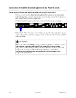
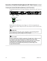
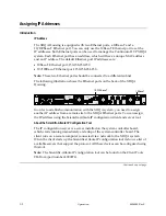
RF Output Connectors
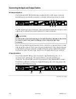
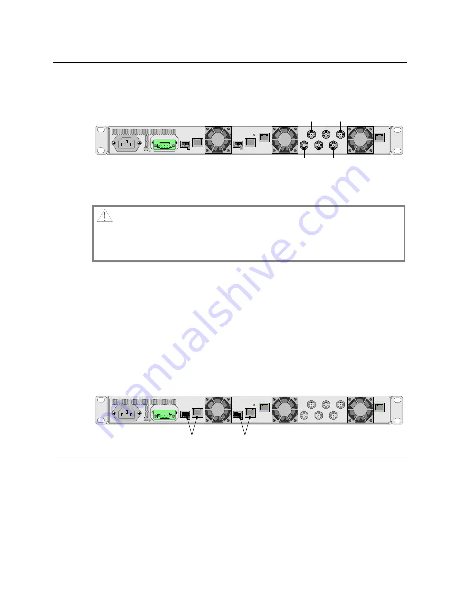
The Continuum DVP XDQA Housing
is equipped with six RF output connectors.
Each RF output is internally connected to a Dual QAM Card by means of a cable.
FAN 1
FAN 2
FAN 3
GbE 1
GbE 2
10/100bT
10bT
1
4
2
3
6
5
RF OUT
BA
C
K
UP
MA
IN
6
5
4
3
2
1
The RF outputs are F-type connectors. These connectors should only accept a coaxial
cable center conductor between 0.56 mm and 1.19 mm in diameter.
CAUTION:
Coaxial cable center conductor larger or smaller than these diameters should not
be used. If used, it may result in damage or loss of signal at the F-type
connector.
Due to the fact that the larger diameter center conductor (e.g. greater than 1.19 mm)
will spread the contacts of an F-type connector further apart, once a larger diameter
is inserted into a F-type connector, a smaller diameter center conductor should not
be used in its place. If used, it may result in loss of signal at the F-type connector.
IP Input Connectors
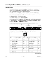
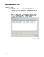
The Continuum DVP XDQA system contains 4 Gigabit Ethernet ports, viz. 2
electrical and 2 optical ports. The electrical GbE connectors are RJ-45 type
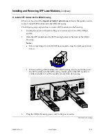
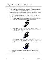
connectors. The optical GbE connector type depends of the installed SFP modules.
The following illustration shows the Gigabit Ethernet ports on the rear panel of the
Continuum DVP XDQA Housing.
FAN 1
FAN 2
FAN 3
GbE 1
GbE 2
10/100bT
10bT
1
4
2
3
6
5
RF OUT
BAC
K
UP
MA
IN
GBE 2
GBE 1
Continued on next page
2-24
Installation
4004949 Rev C
Summary of Contents for Continuum DVP eXtra Dense QAM Array
Page 1: ...Continuum DVP eXtra Dense QAM Array System Guide...
Page 3: ...Continuum DVP eXtra Dense QAM Array System Guide...
Page 18: ...xvi 4004949 Rev C...
Page 20: ......
Page 36: ......
Page 38: ...2 2 Installation 4004949 Rev C...
Page 68: ......
Page 80: ......
Page 86: ......
Page 88: ......
Page 94: ......
Page 100: ......
Page 106: ......
Page 110: ......
Page 111: ......

