background image

SUPERSET 23/23E/PLUS 

      A.3

ad-appen.pm5 P3

scm

APPENDIX

Summary of Contents for Superset 23

Page 1: ...R THROUGHFEED PLANER MOULDER THROUGHFEED PLANER MOULDER MOULURIERE A MOULURIERE A MOULURIERE A MOULURIERE A MOULURIERE AUT UT UT UT UTOMA OMA OMA OMA OMATIQ TIQ TIQ TIQ TIQUE UE UE UE UE PR PR PR PR PROFILFRÄSA OFILFRÄSA OFILFRÄSA OFILFRÄSA OFILFRÄSAUT UT UT UT UTOMA OMA OMA OMA OMAT T T T T MOLDURERA A MOLDURERA A MOLDURERA A MOLDURERA A MOLDURERA AUT UT UT UT UTOMA OMA OMA OMA OMATICA TICA TICA ...

Page 2: ...VUOTO AI ...

Page 3: ...e on how to use the machine contact your local dealer With regard to EC certification the machine is in conformity with council directive 89 392 EEC subsequently integrated by 91 368 EEC 93 44 EEC and 93 68 EEC Pagine totali compresa copertina e retro N 147 Data 01 09 95 LIBRETTO USO E MANUTENZIONE SUPERSET 23 23E 23PLUS UNIFICATO N Bolla B9373 Modifica N Bolla Firma S I T R L 13 05 05 N 000050242...

Page 4: ...INE UNLOADING 2 2 2 2 POSITIONING 2 2 2 3 LEVELLING 2 2 2 4 POWER CONNECTIONS AND EARTHING 2 4 2 5 DUST EXTRACTION SYSTEM CONNECTION 2 6 2 6 PNEUMATIC CONNECTIONS 2 8 2 7 SAFETY DEVICES FITTED 2 10 USE SETTINGS SECTION 3 3 1 CONTROL PANEL 3 2 3 2 PNEUMATIC CONTROL PANEL 3 7 3 3 CONTROL 10 PLUS MICROPROCESSOR CONTROL SUPERSET 23E 3 8 3 4 STARTING THE MACHINE IN AUTOMATIC CYCLE 3 9 3 5 MACHINE STOP ...

Page 5: ... 2 20 3 PNEUMATIC SYSTEM 20 6 20 4 HEAD BELTS 20 8 20 5 REPLACING THE SPEED CHANGE UNIT BELT 20 12 20 6 BELTS BETWEEN SPEED CHANGE UNIT AND GEAR BOXES 20 14 20 7 UNIVERSAL UNIT BELTS 20 16 20 8 ADDA ELECTRO MOTORS 20 16 20 9 SAFETY DEVICE INSPECTION 20 18 20 10 REMOVAL STORAGE DISMANTLING 20 19 20 11 EMERGENCY SITUATIONS 20 19 20 12 TROUBLESHOOTING 20 20 APPENDIX SECTION A SUPERSET 23 LAYOUT 1 A2 ...

Page 6: ...ationswhichfallintotheroutinemaintenance bracket Never perform repairs or maintenance work not indicated in this manual All operations requiring dismantling of parts should be done by authorized engineers In the event of machine parts having to be replaced only ever use SCM original spares having identical features to those which have to be replaced Informationconcerningexclusivelythosemachinesinc...

Page 7: ... to be worked are height 140 mm x width 250 mm Given the possibility of removals from 10 mm to 0 1 mm minimum dimensions can be achieved of machined piece height 6 mm 10 mm with electronic control positioning x width 25 mm with supplementary equipment for narrow pieces dimensions are height 6 mm 10 mm with electronic control positioning x width 15 mm The minimum length of the piece with single fee...

Page 8: ...g spindle Contact with the rotating elements belts pulleys rollers Danger from inhaling of dust in the event of machining without dust extraction system 1 5 MACHINE USE WITH REFERENCE TO THE OPERATOR The control panel features one or more key selector switches These switches enable machine use according to precise safe work setting and logics These switches must only be used by qualified and expre...

Page 9: ...well maintained and free from all materials like shavings etc 4 There must be sufficient general and localized lighting in the place of work 5 Semi finished and finished products must be near the operator s normal work position 6 Experience teaches that you often carry or wear objects which can cause accidents remove rings watches or bracelets fasten sleeves well around wrists remove ties which co...

Page 10: ...able container which must be periodically emptied 17 No attempt must be made to remove scraps or other parts of pieces from the work area while the machine isrunning TOOLS 18 Only prEN847 1 approved tools must be used 19 The instructions of the manufacturer or SCM concerning use settings and repair of toolsmustbecarefully followed 20 The speed limit indicated on the tool must be observed 21 Make s...

Page 11: ...20 140 mm 120 140 mm Minimum and maximum diameter on 2nd lower horizontal spindle 100 200 mm 100 200 mm Profiling capacity on 2nd lower horizontal spindle with 200 mm dia tool 15 mm 15 mm Plane spindle motor power rating 1st lower horizontal 5 5 HP 4 kW 5 5 HP 4 kW Vertical spindle motor power rating 10 HP 7 5 kW 11 HP 8 kW Upper horizontal spindle motor power rating 7 5 HP 5 5 kW 7 5 HP 5 5 kW Lo...

Page 12: ...5 HP 220 V model Automatic delta star start for 5 5 HP motors Feed assembly before surfacer with pneumatic pressure Second feed assembly after universal with pneumatic pressure Feed assembly for 435 mm pieces with pneumatic pressure and mechanical cutout system Tandem feed assembly at infeed before surfacer with pneumatic pressure and quick cutout Tandem feed assembly before right vertical with pn...

Page 13: ...d table Infeed fence with bearings Front pneumatic presser on upper horizontal hood Sliding block vertical presser Horizontal presser before surfacer with control panel pneumatic cutout Supplementary vertical roller presser Front and rear pressure pads on the hood of the universal spindle Static inverter on universal spindle rotation speed varies continually from 1000 to 6000 rpm power rating 2 7 ...

Page 14: ... POWER FOR piece feed 7 5 HP 220 Volt model Automatic star delta start for motors with 5 5 HP rating Feed assembly before surfacer with pneumatic pressure Second feed assembly after universal with pneumatic pressure Feed assembly after upper horizontal complete with tandem feed assembly after second right vertical with quick cutout for drive centre distance of 435 mm with pneumatic pressure and me...

Page 15: ...e 2500 mm Supplementary table with rexilon inserts 2nd lower horizontal unit for max 200 mm blades Cutter with profile above 15 mm depth Chrome plating for grooved table layouts 13 14 15 16 Grooved table for layouts 13 14 15 16 complete with sector cutters on left vertical max dia tool movable under the table 145 mm vertical movement on right vertical max depth profilable under the table 6 mm maxi...

Page 16: ...meter 120 160 mm Digital detector for vertical setting with planer unit decimal indicator Wiring system preset for use of automatic loaders PRESET mod 25 for measuring tool diameter reading is through tool contact on electronic digital indicator centesimalprecision maximummeasurablediameter 250 mm Shaver on first spindle dia 165 mm Supplementary shaver dia 150 mm Supplementary shaver dia 165 mm 2 ...

Page 17: ...NERAL INFORMATION LAYOUTS Legend Lower horizontal unit Upper horizontal unit Presetting of supplementary lower horizontal unit Right vertical unit Left vertical unit Universalunit SUPERSET 23 23E LAYOUTS LAYOUT 1 LAYOUT 2 LAYOUT 5 ...

Page 18: ...GENERAL INFORMATION 1 16 SUPERSET 23 23E PLUS ad gb1 pm5 LAYOUT 6 SUPERSET 23 PLUS LAYOUTS LAYOUT 13 LAYOUT 14 LAYOUT 15 LAYOUT 16 LAYOUT 17 LAYOUT 18 ...

Page 19: ...he figures shown are emission levels and do not necessarily represent definite operating levels While a relation exists between emission levels and exposure levels this cannot be reliably used to determine whether further precautions are required or not The factors affecting real worker exposure levels include durationofexposure environmentcharacteristics otheremissionsources eg thenumberofmachine...

Page 20: ... 16 SUPERSET 23 PLUS 5200 mm layouts 17 18 SUPERSET 23 PLUS 1 10 WORK POSITIONS AND AREAS FIG 1 4 Legend A Control position B Manual loading or other machine link area C Operator unit control and adjustment area D Universal unit control and adjustment area E Manual unloading or other machine link area Distance X must be equal to maximum length of machined piece 500 mm F Perimeter area ...

Page 21: ... P1 scm SECTION 2 INSTALLATION 2 1 MACHINE UNLOADING 2 2 2 2 POSITIONING 2 2 2 3 LEVELLING 2 2 2 4 POWER CONNECTIONS AND EARTHING 2 4 2 5 DUST EXTRACTION SYSTEM CONNECTION 2 6 2 6 PNEUMATIC CONNECTIONS 2 8 2 7 SAFETY DEVICES FITTED 2 10 ...

Page 22: ...s well as easy maintenanceaccess Theminimumfreedistancearoundthemachineshouldbe1000mm exceptintheoperator start up and adjustments area where the distance must be 1500 mm and in the outfeed operator position where the distance must be equal to the maximum length of the machined piece plus 500 mm Check the floor is sound non deformable material is best with concrete floor recommended so the machine...

Page 23: ... scm 2 1 S C M 1700 1700 1 8 5 0 B B P D A C 1 7 0 0 LIFTINGDIAGRAMWITHFORKLIFTTRUCKOF SUPERSET WITH OR WITHOUT UNIVERSAL UNIT LIFTING DIAGRAM WITH CABLES SUPERSET WITH UNIVERSAL UNIT LIFTINGDIAGRAMWITHCABLES SUPERSET WITHOUT UNIVERSALUNIT ...

Page 24: ...on the identification plate in fig 2 2 the machine is however able to adapt to higher or lower voltages with a tolerance range of 5 eg a machine with operating voltage V 380 has a tolerance range from 360 to 400 V Beyond this range regulate the power voltage Read the total power input Amp on the machine identification plate fig 1 2 Consultthetablebelowforcorrectcablecrosssectionareaandtofit DELAYE...

Page 25: ...SUPERSET 23 23E PLUS 2 5 ad i2 pm5 P5 scm 2 2 PE L2 L3 L1 N COM2 3 125 007 Ec 0 G G ...

Page 26: ... 1 1010 839 4 layout 1 1 2 3 4 3943 4 1st right vertical spindle 2 855 936 6 layout 2 1 2 3 4 5 4733 7 left vertical spindle 3 741 901 2 layout 5 1 2 3 4 6 4787 2 1st upper horizontal spindle 4 976 1266 2 layout 6 1 2 3 4 5 6 5577 5 universal spindle 5 723 790 3 layout 13 1 2 3 4 6 7 5727 3 2st lower horizontal spindle 6 924 843 8 layout 14 1 2 3 4 5 6 7 6517 6 2st right vertical spindle 7 850 940...

Page 27: ...SUPERSET 23 23E PLUS 2 7 ad i2 pm5 P7 scm 2 5 N L 125 012 Ez 0 U U 2 4 N ...

Page 28: ... amount of material removed and type of material being machined Connections should be made as follows 1 Connect the pipe from the centralized system to pipe fitting E fig 2 6 2 Set the pressure by means of regulator R Superset 23 plus The padlockable valve A fig 2 6 lets the compressed air into the pneumatic system This valve opens when 1 it is not padlocked and the tang L is fully pushed in 2 The...

Page 29: ...SUPERSET 23 23E PLUS 2 9 ad i2 pm5 P9 scm 2 6 SUPERSET 23 SUPERSET 23E SUPERSET 23 PLUS P Q A E E E E E R R B B B B B L L L P Q A P Q A T T Z Z ...

Page 30: ... connected after adjustments have been made 11 Guards M fig 2 7 positioned in front of the vertical heads 12 Self braking motors on the heads 13 Filter unit and air reducing valve N fig 2 7 with padlockable stopcock and automatic air release 14 Hand control unit O fig 2 7 15 All doors are closed with screws P fig 2 7 16 Piecefeedwheelspeedlimitingdevice microswitch Rfig 2 7 preventsfeedspeedsofove...

Page 31: ...SUPERSET 23 23E PLUS 2 11 ad i2 pm5 P11 scm 2 7 F O B X 125 013 Ez 0 M M G P H H D N Q C E S T U 125 019 Ez 0 R 125 014 Ez 0 L C A A1 W V ...

Page 32: ...INSTALLATION 2 12 SUPERSET 23 23E PLUS ad i2 pm5 P12 scm ...

Page 33: ...GS 3 1 CONTROL PANEL 3 2 3 2 PNEUMATIC CONTROL PANEL 3 7 3 3 CONTROL 10 PLUS MICROPROCESSOR CONTROL SUPERSET 23E 3 8 3 4 STARTING THE MACHINE IN AUTOMATIC CYCLE 3 9 3 5 MACHINE STOP 3 9 3 6 EMERGENCY STOP 3 9 3 7 SELF BRAKING MOTOR 3 10 3 8 MODE SELECTOR SWITCH OPERATION 3 10 ...

Page 34: ...n of selector switch 4 O off I on Button pressed power off Consult the attached user manual feed rollers enabled feed rollers and upper horizontal unit enabled 1 feed rollers and 1st upper horizontal unit enabled 2 2nd upper horizontal unit enabled 1 1st upper horizontal unit enabled 2 feed rollers and 2nd upper horizontal unit enabled left vertical unit enabled 1 1st upper horizontal unitand or t...

Page 35: ...ition Press to start Press to start Press to stop Press to start Press to adjust Press to start Press to start Starts the motorized control of the upper horizontal unit and or the feed or the left vertical unit according to the position of selector 4 Starts the micrometric control of the upper horizontal unit and the feed or the left vertical unit according to the position of selector switch 4 and...

Page 36: ...t verticalunit Starts rotation of left verticalunit Starts rotation of 1st upper horizontal unit Starts rotation of 2nd lower horizontal unit Starts rotation of 2nd right vertical unit Starts rotation of 2nd upper horizontal unit Starts rotation of right and left verticalunit Enablesandselectsthedirectionof rotation of the universalunit Signals motor brake release condition selector switch 24 in p...

Page 37: ... height Startshorizontalpositioningofthe left vertical unit in semiautomatic mode Selects the operating mode of the left vertical unit Signals enabling of piece loading Signalsdisablingofpieceloading Signalsleftverticalunitlubrication pump oil level Stops universal unit movement manual cycle automatic cycle Indicator on power on O positioner stopped increases piece width decreases piece width auto...

Page 38: ...cal unit Stops movement of 1st lower horizontal unit Stops movement of 2nd upper horizontal unit Turn lights in cab on and off Singleorin linemachine operation presetting Enables operation of hydraulic pump and programmer Selects direction of rotation of 2nd right vertical unit Selects direction of rotation of 2nd upper horizontal unit Enablesanddisables lubrication of the left vertical unit Press...

Page 39: ...tion Regulatesthepressureoftherubber feed rollers after the upper horizontal unit Shows the pressure of the rubber feed rollers Regulates the pressure of the sprocket feed rollers before the upper horizontal unit Shows the pressure of the sprocket feed rollers Regulates the pressure of the sprocketfeedrollerbeforetheplane lower horizontal Shows the pressure of the sprocket feed roller Regulatesthe...

Page 40: ...nd profiling tools possibility of selecting in manual mode MDI any section besides the programmes stored possibility of changing the selected programme positioning dimensions automatic axes setting alarmmessagesconcerninganymalfunctions reset of various functions four language conversation with keyboard selection It features dustproof function keyboard rear lit liquid crystal LCD alphanumeric disp...

Page 41: ...lectronic system with microprocessor control SUPERSET 23E model Disable the heads that are not to be switched on only for layouts 5 6 13 14 15 16 17 18 Turn the selector switch 23 to the desired position to switch on the universal unit only for layouts 2 6 14 16 18 Start the heads by pressing buttons 15 16 17 18 and the buttons 19 20 21 if fitted Press button 13 or 14 to start the universal unit o...

Page 42: ...icktoolstopdonotcontaincarcinogenicsubstances 3 8 MODE SELECTOR SWITCH OPERATION The mode selector switch is of the key type MANUAL MODE For manual mode turn the switch 28 3 1 to position In manual mode 1 The hood can be opened after 20 sec 2 The feed only jog operates only if set at a speed below or equal to 15 m min forward if the heads are on in reverse only if the heads are off 3 In case of st...

Page 43: ...S SUPERSET 23 23E PLUS 4 1 ad i4_1 P1 scm SECTION 4 HEADS 4 1 TOOL ADJUSTMENT AND SPINDLE CLAMPING 4 2 4 2 HEADS 4 8 4 3 FEED ASSEMBLY 4 20 4 4 INFEED TABLE AND FENCE 4 24 4 5 FENCES 4 24 4 6 PRESSERS 4 32 ...

Page 44: ... fig 4 1b Subsequently tighten the screws well starting with those in the middle and going on to the others alternatively N B The blade can protrude by a maximum 1 5 mm from the spindle body fig 4 1b The blades Z fig 4 1b can be used up to a minimum height of 22 mm NOTE Inthecaseofmachineswithshavers takecarethebladesintersectperfectlywiththecutter Toposition the plane blades it is better to first...

Page 45: ...HEADS SUPERSET 23 23E PLUS 4 3 ad i4_1 P3 scm D L C M 4 1 A 4 1a 4 1b max 1 5mm min 22mm T Z ...

Page 46: ... Ø 120 Ø 130 Ø 140 Ø 150 Ø 160 Ø 170 Ø 180 Ø 100 Ø 110 Ø 190 Ø 200 L 140 L 150 1 2 8300 RPM SPINDLE Ø 40 mm NOTE For vertical units with 6000 RPM and spindles ø 40 5 mm 1 13 16 and vertical units 8300 RPM and spindles ø 50 mm 1 13 16 ALLSOLUTIONSAREPOSSIBLEFORTOOLSWITHSTEEL OR ALUMINIUM BODY ...

Page 47: ...L 190L 180 L 170 L 160 L 150 L 100 L 110 6000 RPM SPINDLE Ø 1 13 16 2 1 L 230 L 220 L 210L 200 Ø 120 Ø 130 Ø 140 Ø 150 Ø 160 Ø 170 Ø 180 Ø 100 Ø 110 Ø 190 Ø 200 L 240 L 250 L 130 L 120 L 140 L 190L 180 L 170 L 160 L 150 L 100 L 110 6000 RPM SPINDLE Ø 50 mm 2 1 L 230 L 220 L 210L 200 Ø 120 Ø 130 Ø 140 Ø 150 Ø 160 Ø 170 Ø 180 Ø 100 Ø 110 Ø 200 L 240 L 250 L 130 L 120 L 140 L 190L 180 L 170 L 160 L 1...

Page 48: ...80 L 170 L 160 L 150 L 100 L 110 Ø 190 2 3 1 8300 RPM SPINDLE Ø 1 13 16 L 230 L 220 L 210L 200 Ø 120 Ø 130 Ø 140 Ø 150 Ø 160 Ø 170 Ø 180 Ø 100 Ø 110 Ø 200 L 240 L 250 L 130 L 120 L 140 L 190L 180 L 170 L 160 L 150 L 100 L 110 Ø 190 8300 RPM SPINDLE Ø 50 mm 2 1 3 L 230 L 220 L 210L 200 Ø 120 Ø 130 Ø 140 Ø 150 Ø 160 Ø 170 Ø 180 Ø 100 Ø 110 Ø 200 L 240 L 250 L 130 L 120 L 140 L 190L 180 L 170 L 160 L...

Page 49: ...00 Ø 190 Ø 120 Ø 130 Ø 140 Ø 150 Ø 160 Ø 170 Ø 180 Ø 100 Ø 110 Ø 200 Ø 190 Ø 120 Ø 130 Ø 140 Ø 150 Ø 160 Ø 170 Ø 180 Ø 100 Ø 110 Ø 200 Ø 190 L 230 L 220 L 210L 200 L 240 L 130 L 120 L 140 L 190L 180 L 170 L 160 L 150 L 100 L 110 L 230 L 220 L 210L 200 L 130 L 120 L 140 L 190L 180 L 170 L 160 L 150 L 100 L 110 L 230 L 220 L 210L 200 L 240 L 130 L 120 L 140 L 190L 180 L 170 L 160 L 150 L 100 L 110 L...

Page 50: ...sted against the fence G and the plane turned manually so the shaver skims the strip Every time the blades of the shaver are sharpened make sure the shaver is always aligned with the fence G fig 4 3 To perform adjustments the spindle can be moved vertically by means of screws C fig 4 4 after releasing the handle B The exact setting is always reached moving upwards After adjustment check the alignm...

Page 51: ...HEADS SUPERSET 23 23E PLUS 4 9 ad i4_2 P9 scm 4 5 4 4 A D C B S SUP310 SUP311_L V ...

Page 52: ... table is at the same height as the worktable Fasten handles F and E NOTE The exact setting is always achieved moving upwards Vertical adjustment must always be made with the unit turning Transverse adjustment The numeric display L fig 4 7 shows the diameter of the tool fitted When fitting tools of different diameter loosen the handle E fig 4 7 turn screw H clockwise with the crank provided if the...

Page 53: ...HEADS SUPERSET 23 23E PLUS 4 11 ad i4_2 P11 scm SUP312_L 4 7 4 6 B A C 125 015 Ez 0 S L H G E I F ...

Page 54: ...dicates that the tool support table is at the same height as the worktable Fasten handles M and Q NOTE The exact setting is always achieved moving upwards Vertical adjustment shouldalways be made with the unit turning Transverse adjustment with manual device This adjustment determines the desired piece width Loosen handle Q fig 4 8 turn screw O clockwise using the crank provided to reduce piece wi...

Page 55: ...HEADS SUPERSET 23 23E PLUS 4 13 ad i4_2 P13 scm 4 9 4 8 SUP314_L R A B T S U O N M Q P C SUP3 3 ...

Page 56: ...ermits automatic positioning of the spindle according to the work parameters selected see 3 3 and attached documentation Fitting of tools with different diameter to previous ones remove the guard P fig 4 8 remove the tool see para 4 1 loosen the handle U turn using crank provided screw S until the indicator T shows the minimum diameter of the new tool previously determined using Preset equipment s...

Page 57: ...HEADS SUPERSET 23 23E PLUS 4 15 ad i4_2 P15 scm 4 10 3 18 D 7 5 4 6 ...

Page 58: ... 23E electronic device Permits automatic positioning of the spindle according to the work parameters set see 3 3 and attached documentation Vertical adjustment of 1st upper horizontal spindle using micrometric device SUPERSET 23 PLUS This adjustment enables the piece thickness to be defined Turn the selector switch 4 bis 3 1 to position 1 Press button 6 to bring the unit to a lower setting than th...

Page 59: ...HEADS SUPERSET 23 23E PLUS 4 17 ad i4_3 P17 scm 4 12 SUP323_L F P A G D Q Q E 4 11 C SUP3 3 A B ...

Page 60: ...ssible to fit tools with min dia 100 mm and max dia 200 mm Vertical adjustment Loosen handle G fig 4 13 Turnscrew H counterclockwisetoraisetheunit untiltheminimumtooldiameter previouslydeterminedwith the PRESET appears on numeric display I NOTE the exact setting must always be reached moving upwards Subsequently fasten handle G Transverse adjustment Loosen screw H fig 4 14 Turn using the crank pro...

Page 61: ...HEADS SUPERSET 23 23E PLUS 4 19 ad i4_3 P19 scm 4 13 4 14 L H G H SUP325_L SUP326_L I A S D M ...

Page 62: ...he machine is equipped with wheels sprocket and rubber of different thickness 20 and 50 mm More than one wheel can be fitted to the same spindle The travel of both the traverse and the Upper Horizontals is delimited by limit switches and stops G L E F fig 4 16 These are adjusted during machine testing and settings should not be changed 4 3 1 ADJUSTMENT OF PRESSURE OF SPROCKET WHEELS BEFORE THE UPP...

Page 63: ...HEADS SUPERSET 23 23E PLUS 4 21 ad i4_3 P21 scm 4 16 4 15 E F L G S U P 3 6 1 _ L B1 B 125 016 Ez 0 V ...

Page 64: ...are positioned during testing 3mm under the tool diameter of the Upper Horizontal Normally the position of the drive wheels should not be changed If adjustment has to be made loosen the nut at point A fig 4 17 in order to operate on the adjustment dowel Subsequently tighten the nut A The first sprocket wheel can be excluded by raising lever E fig 4 15 The maximum travel of the wheels is 30 mm ...

Page 65: ...HEADS SUPERSET 23 23E PLUS 4 23 ad i4_3 P23 scm SUP353_L A 4 17 ...

Page 66: ...Position the fence F fig 4 19 depending on the tool diameter by loosening screws G Maintain a distance from the tool cutting edge of 4 5 mm Before refastening the screws check perfect alignment with the other right fences 4 5 2 FENCE AT OUTFEED OF LEFT VERTICAL UNIT SUPERSET 23 23E The fence I fig 4 20 is aligned with minimum tool diameter of the left vertical unit during testing This setting is n...

Page 67: ...HEADS SUPERSET 23 23E PLUS 4 25 ad i4_3 P25 scm SUP312_L F G 4 20 SUP342_L Y I X K L N 4 19 ...

Page 68: ...should be made as follows Transverse positioning loosen the screws A fig 4 21 and turn the screw F fig 4 2 1 using the tool provided Height positioning loosen the screws B turn knobs C and retighten screws B To achieve perfect parallelism with the right fence loosen screws X To adjust the pressure of the fence turn screws Y fig 4 20 4 5 4 FENCE AT OUTFEED For transverse adjustment of the fence G f...

Page 69: ...HEADS SUPERSET 23 23E PLUS 4 27 ad i4_3 P27 scm 4 22 M G A SUP331_L 4 21 X X B C A D E 125 017 Ez 0 F ...

Page 70: ...rtially work the right side of the piece The 1st right vertical unit is always moved together with the fence to ensure the tool is always aligned with the fence G fig 4 24 If the tool U is replaced by another of different diameter the tool will have to be re aligned with the fence G in the following way 1 Turn the screw V until a greater diameter than the real diameter of the new tool appears on t...

Page 71: ...HEADS SUPERSET 23 23E PLUS 4 29 ad i4_3 P29 scm 4 24 G U V I ...

Page 72: ...ositioning the fences G and tightening screws B 4 5 6 LEFT PARALLELOGRAM FENCE fig 4 2 7 1 Transverse adjustment of the fence is made by means of adjustment dowel F after loosening the nut and locknut Subsequently retighten the above parts 2 The pressure load on spring M is adjusted by means of nut T after loosening the locknut Subsequently retighten ...

Page 73: ...HEADS SUPERSET 23 23E PLUS 4 31 ad i4_3 P31 scm 4 26 4 27 F M T G B ...

Page 74: ... testing and does not normallyrequireadjustment To make adjustment loosen screws N and move the presser body Set the pressure pad P parallel to the right fence by means of stop screw Q fig 4 29 The screw R acts as a stop and must provide a maximum pressure pad travel of 3 mm Whenthepresserisatmaximumtravel itsendmustbeatasafetydistanceof5mmfrommaximumtooldiameter This setting is made by loosening ...

Page 75: ...HEADS SUPERSET 23 23E PLUS 4 33 ad i4_3 P33 scm 4 31 4 30 V Y K S T R SUP348 SUP347 4 29 SUP340_L N S Q R P ...

Page 76: ...HEADS 4 34 SUPERSET 23 23E PLUS ad i4_3 P34 scm ...

Page 77: ...SECTION 10 ADJUSTMENTS AND USE OF OPTIONAL UNITS 10 1 SUPPLEMENTARY FEED ASSEMBLIES 10 2 10 2 OPTIONALS ON INFEED TABLE AND FENCE 10 6 10 3 PRESSERS 10 8 10 4 LEFT VERTICAL UNIT AUTOMATIC POSITIONING DEVICE 10 14 10 5 UNIVERSAL SPINDLE 10 18 10 6 PRESET 10 30 ...

Page 78: ...ertedintheworktable mustprotrudefromthetablebyabout 0 25 mm Adjustment is made by means of dowel P after loosening the locknut M The pressure on the piece can be adjusted by means of nut X fig 10 2 10 1 3 FEED ROLLER IN WORKTABLE The supplementary feed roller C inserted in the worktable fig 10 4 must protrude from the table by about 0 04 mm This roller is also set during testing and does not norma...

Page 79: ...OPTIONAL UNITS SUPERSET 23 23E PLUS 10 3 ad i10_1 P3 scm 10 4 B C A SUP359_L 10 3 K SUP347 ...

Page 80: ...mple to replace the drive wheels proceed as follows Disconnect the air feed tube T by pulling out the quick coupling Loosen screw V and the stop ring screw F Remove the stop ring The tandem assembly can now be removed 10 1 5 1ST SPROCKET WHEEL PRESSURE ADJUSTMENT By means of regulator A fig 10 5 the pressure displayed on the pressure gauge A1 can be changed Proper pressure setting is 2 bar 10 1 6 ...

Page 81: ...OPTIONAL UNITS SUPERSET 23 23E PLUS 10 5 ad i10_1 P5 scm 10 6 125 016Ez 0 A1 C1 C A 10 m m 125 018Ez 0 10 5 ...

Page 82: ...f the liquid is at minimum the red indicator light S comes on and the pump stops The green indicator E indicates pump on the yellow indicator G indicates lubrication cycle operating The pump can be cut out by means of switch I 10 2 2 AUTOMATIC LEFT VERTICAL UNIT LUBRICATION PUMP Lubricationintervalsaresetbymeansoftheelectromechanicalprogrammer Afig 10 7b fittedinsidethepump To carry out a pumping ...

Page 83: ...OPTIONAL UNITS SUPERSET 23 23E PLUS 10 7 ad i10_1 P7 scm 10 8 SUP3 8 G L C 10 7a I R SUP411_M A E P S G 10 7a NOV16_21 P A ...

Page 84: ... and B fig 10 9 can be positioned lengthways according to the tool diameter on the Right Vertical To carry out this operation remove screws C and fasten then in the adjacent holes 10 3 2 VERTICAL PRESSERS The pressers D fig 10 10 can be height adjusted by means of screws E The wheels must be positioned at the same height as the drive wheels and aligned to these The pressure applied can be adjusted...

Page 85: ...OPTIONAL UNITS SUPERSET 23 23E PLUS 10 9 ad i10_1 P9 scm SUP3331_L 10 10 E D X ...

Page 86: ...presser can be brought closer to the tool by turning the screws which fasten the presser in other holes provided 10 3 4 PNEUMATIC PRESSERS When the presser is pneumatic C fig 10 12 it must be height positioned after loosening the screws S The pressure on the piece can be adjusted by means of regulator knob D fig 10 13 Normal settings 1 1 5 atm read on pressure gauge D1 The regulator E and the pres...

Page 87: ...OPTIONAL UNITS SUPERSET 23 23E PLUS 10 11 ad i10_1 P11 scm 10 12 10 13 SUP3 5_L S C E D1 E1 D SUP3 4_L ...

Page 88: ...djustment loosen screws A Adjustment of pressure on piece turn knobs B 10 3 6 KIT FOR CUTTING RIGHT GLAZING BEAD ON UPPER HORIZONTAL SPINDLE This optional device is used to make the glazing bead from the profiling of frame uprights and crosspieces The kit consists of a rear presser unit A fig 10 16 different from the standard model of a bead recovery unit B and of a right fence C already prepared ...

Page 89: ...OPTIONAL UNITS SUPERSET 23 23E PLUS 10 13 ad i10_1 P13 scm 10 15 C A B Z S U P 3 5 1 10 16 A B C ...

Page 90: ...ches the drive wheels with the pressers at the sides of the hood Loosen nuts A fig 10 17 Turnthescrew B untilthelimitswitchwhichpreventscollisionoftheUnitwiththedrivewheelsistriggered Retighten the nuts A AUTOMATIC POSITIONING Turn the selector switch 34 3 1 to position and check the green indicator light 35 is on Introduce a piece in feed direction so it pushes forward lever A fig 10 18 The red i...

Page 91: ...OPTIONAL UNITS SUPERSET 23 23E PLUS 10 15 ad i10_1 P15 scm 10 17 SUP317 A B A B S U P 3 1 8 10 18 ...

Page 92: ...ex glass L SEMIAUTOMATIC POSITIONING Turn selector switch 34 3 1 to position Turn selector switch 33 to position to bring the Unit closer to the right fences and to position to move it away from the right fences MANUAL POSITIONING Turn the selector switch 34 3 1 to position brake motor off Position the Unit by means of handwheel V fig 10 21 and read the setting on the display 30 3 1 Return the sel...

Page 93: ...OPTIONAL UNITS SUPERSET 23 23E PLUS 10 17 ad i10_1 P17 scm 10 20 10 21 SUP321 SUP3 20 V L P ...

Page 94: ...ions between the above almost totally covering 360 It can accept tools with min dia 100 mm and max dia 200 mm To reach the spindle simply loosen knobs A and remove B of hood 10 5 1 ADJUSTMENTS A Transverse positioning loosen knob C turn screw D using crank provided clockwise to move the spindle away from the Operator Read movements on display E NOTE The exact position is always achieved by turning...

Page 95: ...OPTIONAL UNITS SUPERSET 23 23E PLUS 10 19 ad i10_2 P19 scm 10 22 E C D A B SUP327_L ...

Page 96: ...he movements on the display H NOTE The exact position is always achieved upwards Tighten F C Rotation Turn screw L fig 10 23 counterclockwise to unblock rotation Turn screw M counterclockwise to rotate the unit from 0 Upper Horizontal to 90 Left Vertical Read the movements on the display N displays degrees and tenths of degree Turn L clockwise to reblock ...

Page 97: ...OPTIONAL UNITS SUPERSET 23 23E PLUS 10 21 ad i10_2 P21 scm 10 23 L N M G F H SUP328_L ...

Page 98: ...set the display E Align the spindle axis with the right fence Unscrew the dowel which holds the ring nut F and turn the latter manually until a series of zeros appears on the display Fasten the dowel which holds the ring nut NOTE 0 is achieved by turning the ring nut in the same direction as the screw D to attain exact positioning in this case clockwise Zero setthedisplay Hfig 10 23 Whentheworktab...

Page 99: ...OPTIONAL UNITS SUPERSET 23 23E PLUS 10 23 ad i10_2 P23 scm 10 25 sup327_l T S E F D ...

Page 100: ...ndle to right vertical position Refit the dust extraction hood turned by 180 as shown in fig 10 26 and position the curve Fit the tables C D E fig 10 27 positioning the table D according to the work to be done Align the left fence U fig 10 26 with fence V Fasten handles Z Adjust the right fences X and Y loosening the screws which fasten them at the rear according to the diameter of the tool used A...

Page 101: ...OPTIONAL UNITS SUPERSET 23 23E PLUS 10 25 ad i10_2 P25 scm 10 26 SUP331_L Y W X Z R U V ...

Page 102: ...ig 10 27 and pull out bar B to remove the pressers W Remove fence U Remove tables C D E Turn screw M fig 10 28 clockwise after releasing it chapter 10 5 1 to bring the unit into position shown in fig 10 28 The display N must show 0 Fit the tables for working with horizontal units F and G fig 10 28 Refit the hood if removed Refit the fence U ...

Page 103: ...OPTIONAL UNITS SUPERSET 23 23E PLUS 10 27 ad i10_2 P27 scm 10 28 M N G F U ...

Page 104: ...hims T fig 10 30 to be positioned under table G permit aligning the latter to the edge of the plane Refit fence U fig 10 28 Refit pressers W 10 5 6 USE AS TILTED SPINDLE Fig 10 31 shows the angular sectors which can be covered with the universal spindle starting from various standard positions Thefigureshowsmaximumpossiblerotationswithapiecewidthof120mm thickness60mmandtooldiameter 125mm Withlarge...

Page 105: ...OPTIONAL UNITS SUPERSET 23 23E PLUS 10 29 ad i10_2 P29 scm 10 31 10 30 G T Tool diameter 125 mm sup335_l 60 90 R I G H T FENCE W O R K T A B L E ...

Page 106: ...ng B up close to a tool blade and read the measurement shown on H 4 Tool diameter twice the measurement read on H To height adjust a Loosen the rear knob W for large adjustments b turn knob C for precision adjustments Keep clean rule D of the instrument Button G sets the measurement shown on H Button E changes the display to mm or inches The instrument works with watch batteries located alongside ...

Page 107: ...OPTIONAL UNITS SUPERSET 23 23E PLUS 10 31 ad i10_2 P31 scm 10 32 R A U H F W C D B K E ...

Page 108: ...OPTIONAL UNITS 10 32 SUPERSET 23 23E PLUS ad i10_2 P32 scm ...

Page 109: ...SUPERSET 23 23E PLUS 19 1 19 SECTION 19 SELF BRAKING MOTOR ...

Page 110: ... material ring F which is subject to wear Maximum wear for this friction ring is 3 mm Replacement of the ring should be done exclusively by the technical staff of your dealer Adjustment of braking unit Any drop in braking performance is indicated by the time needed by the spindle to come to a complete halt maximum time 10 seconds To correctly reset the braking couple proceed as follows remove the ...

Page 111: ...SUPERSET 23 23E PLUS 19 3 19 19 1 19 2 freno1 freno2 ...

Page 112: ...SELF BRAKING MOTOR 19 4 SUPERSET 23 23E PLUS SEZ I19 ...

Page 113: ...ATION 20 2 20 3 PNEUMATIC SYSTEM 20 6 20 4 HEAD BELTS 20 8 20 5 REPLACING THE SPEED CHANGE UNIT BELT 20 12 20 6 BELTS BETWEEN SPEED CHANGE UNIT AND GEAR BOXES 20 14 20 7 UNIVERSAL UNIT BELTS 20 16 20 8 SAFETY DEVICE INSPECTION 20 18 20 9 REMOVAL STORAGE DISMANTLING 20 19 20 10 EMERGENCY SITUATIONS 20 19 20 11 TROUBLESHOOTING 20 20 ...

Page 114: ...t extraction hoods check there are no blockages and clean with a strong jet of compressed air see para 2 4 For better cleaning and any servicing access is through the rear of the machine remove panels P fig 20 0 loosen screw V raise the panel and remove from its supports Important After cleaning or servicing remember to replace the panels P 20 2 PERIODICAL LUBRICATION All the machine bearings are ...

Page 115: ...MAINTENANCE SUPERSET 23 23E PLUS 20 3 ad i20_1 P3 scm 20 3 7 1 3 2 4 5 G 6 20 2 20 1 ...

Page 116: ... 20 7 underthedrivewheeldrivinggear thereisalubricatorforeachfeedshaft Every2500work hours pump about 3 cu cm of AGIP GR MU EP0 grease or equivalent through each lubricator The gear boxes should be topped up with AGIP BLASIA 320 type oil or equivalent after unscrewing cap K fig 20 7 Check the level through cap W ...

Page 117: ...MAINTENANCE SUPERSET 23 23E PLUS 20 5 ad i20_1 P5 scm 20 8 17 18 16 15 19 S U P 4 7_L K W 13 14 20 7 ...

Page 118: ...apacity Lubricator B fig 20 10 Supplies atomized oil to the pneumatic cylinders Every day before starting work make sure the level of the oil in the bulb is at least 1 3 total capacity Top up by unscrewing the bulb after releasing pressure from the pneumatic system with oil type AGIP OSO 32 MOBIL DTE 21 or equivalents With the machine running at normal working speed check through the spy bell R th...

Page 119: ...MAINTENANCE SUPERSET 23 23E PLUS 20 7 ad i20_1 P7 scm 20 10 20 9 A B SUP4 9_L V V T T H H D R D R ...

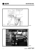
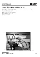
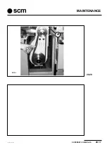
Page 120: ...e distance between the 2 lines becomes 102 mm subsequently refit the locknut and the 4 screws Following this same procedure reset the belts every 1000 hours operation or at the first sign of slipping To replace the belt Horizontal units a remove the guard Q fig 20 11 b loosen the screws A c move the motor just enough to take the belt off the pulleys d fit the new belt and set the tension as descri...

Page 121: ...MAINTENANCE SUPERSET 23 23E PLUS 20 9 ad i20_1 P9 scm 20 11 20 12 SUP413_L A M N Q A SUP414_L V G ...

Page 122: ...otor and adjust the dowel Q fig 20 13 to centre the belt on the pulley Right and Left Vertical units Superset 23 PLUS A Loosen screw V fig 20 12 after loosening locknut G B Remove the belt and fit the new one C Turn screw V to tighten the belt and fasten locknut G Start the motor and adjust the dowel Q fig 20 13 to centre the belt on the pulley 1 MOTOR PULLEY 2 GUIDE PULLEY IDLER 3 RIGHT VERTICAL ...

Page 123: ...MAINTENANCE SUPERSET 23 23E PLUS 20 11 ad i20_1 P11 scm B E D A sup416_m 20 14 SUP311_L 20 13 Q ...

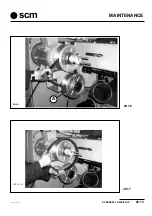
Page 124: ...osen the 3 locknuts A fig 20 14 and the 3 dowels B to free the end of the cable C fig 20 15 Remove the self braking nuts D fig 20 14 Loosen the dowels E fig 20 14 Remove the bracket F 20 15 Pull the belt so pulley A fig 20 16 widens Remove the belt see fig 20 17 To fit proceed inversely F C SUP417_m 20 15 ...

Page 125: ...MAINTENANCE SUPERSET 23 23E PLUS 20 13 ad i20_2 pm5 P13 scm 20 16 20 17 A S U P 4 1 8 _ M SUP419_M ...

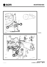
Page 126: ...tion and subsequently every 500 hours Loosen the nuts A fig 20 18 and tighten nuts B as required then refasten nuts A Tightening is correct when after applying a pressure P of 2 kg on the belt a camber f 3 5 mm is obtained REPLACEMENT Loosen nuts A fig 20 18 Unscrew nuts B Replace the belts Screw up nuts B until correct tension is achieved and then tighten nuts A ...

Page 127: ...MAINTENANCE SUPERSET 23 23E PLUS 20 15 ad i20_2 pm5 P15 scm C D A B SUP333_L 20 18 20 19 SUP420_L B A ...

Page 128: ...e right and left Loosen the 4 screws A fig 20 20 Loosen the locknut C fig 20 19 Loosen as far as necessary screw D Refasten locknut C and the 4 screws A fig 20 19 Tensioniscorrectwhen afterapplyingapressure P of1 5kgoneachbelt halfwayalongthestraightsection a camber f 5 mm is obtained REPLACEMENT Remove the guard A fig 20 19 Loosen the screws A fig 20 20 Loosen the locknut C and the screw D fig 20...

Page 129: ...MAINTENANCE SUPERSET 23 23E PLUS 20 17 ad i20_2 pm5 P17 scm 20 20 S U P 4 2 2 _ M A ...

Page 130: ...ency of the micro interlock and block electromagnet on the hood by means of an operating test a withthemachineinnormalautomaticmodeoperatingconditions thehoodshouldnotopen b by means of the key selector switch pass from automatic to manual mode After about 20 seconds check the hood should open c with the hood open pass from manual mode to automatic mode The heads and feed assemblies should not sta...

Page 131: ... dismantling separate ferrous from plastic materials and send for scrapping 20 10 EMERGENCY SITUA 20 10 EMERGENCY SITUA 20 10 EMERGENCY SITUA 20 10 EMERGENCY SITUA 20 10 EMERGENCY SITUATIONS TIONS TIONS TIONS TIONS In case of flooding flooding flooding flooding flooding of the premises in which the machine is operating immediately interrupt the power supply Before restarting work have the machine ...

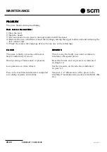
Page 132: ...hine stops during operation CAUSE CAUSE CAUSE CAUSE CAUSE REMEDY REMEDY REMEDY REMEDY REMEDY Power failure on one or more line phases Check there is power on the three phases Auxiliary circuit fuses interrupted or 1 Close the fuse carrier cover If the machine very bad cutting fails to start open the fuse carriers and check their condition If necessary replace A set is supplied in the accessory pac...

Page 133: ...ot aligned Align the spindle and the fence as indicated in with the fence para 4 2 2 PROBLEM PROBLEM PROBLEM PROBLEM PROBLEM Puckering and imperfections on the left side CAUSE CAUSE CAUSE CAUSE CAUSE REMEDY REMEDY REMEDY REMEDY REMEDY The left pressers and outfeed fence are The pressers on the left side of the machine badly set must press the wood by a few millimetres and the outfeed fence must re...

Page 134: ...the left vertical unit 5 Check the reason for stoppage it may be any one of the following CAUSE CAUSE CAUSE CAUSE CAUSE REMEDY REMEDY REMEDY REMEDY REMEDY The piece is faulty presence of knots or Throw away the faulty piece and continue to lack of uniformity of wood machine subsequent pieces Wrong setting of fences and or pressers Reset the fences and or pressers as indicated in chapter 4 Low pres...

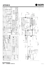
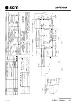
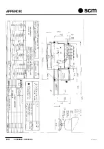
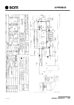
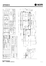
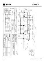
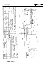
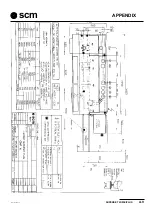
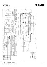
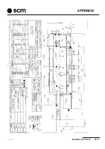
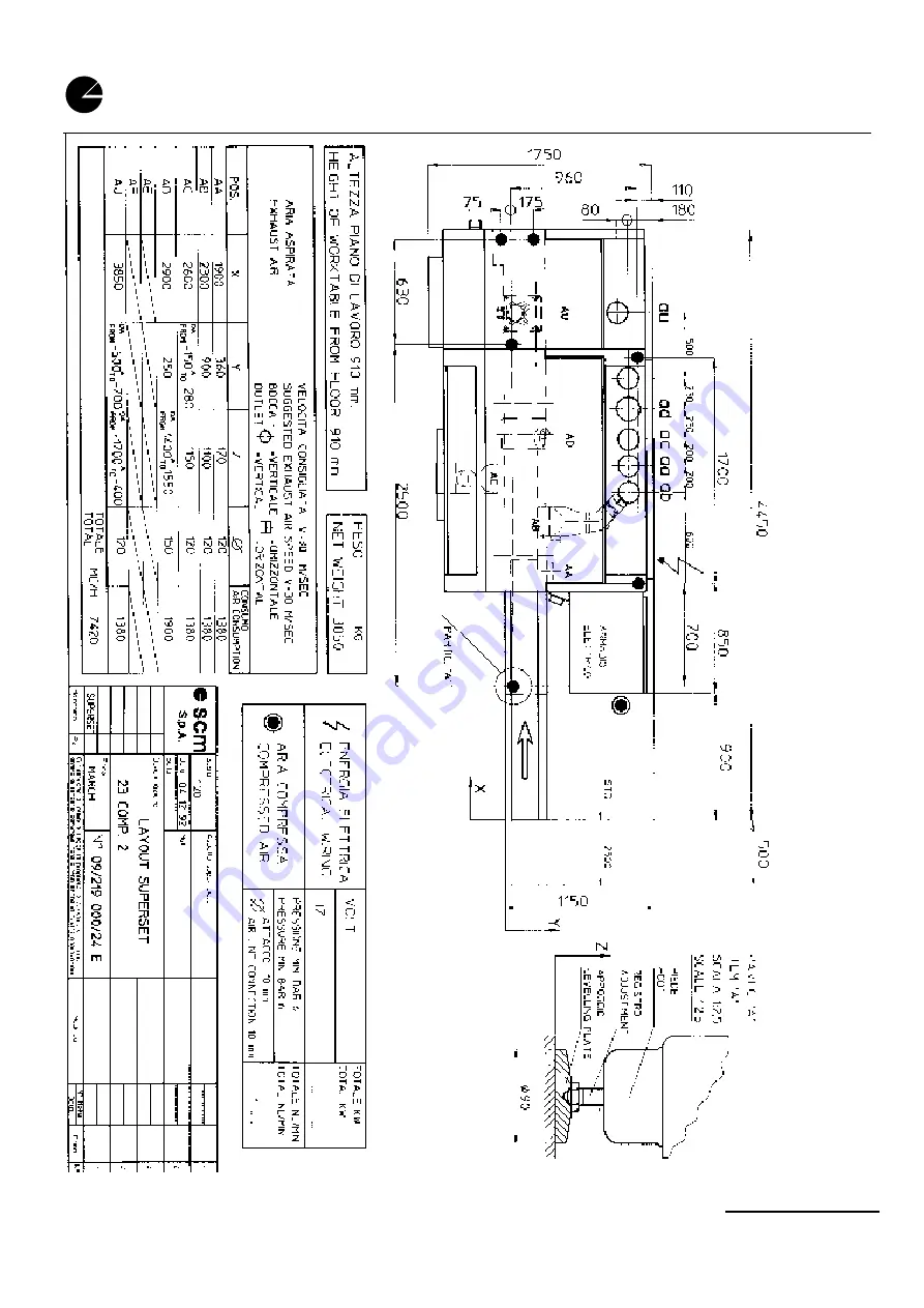
Page 135: ...ECTION A SUPERSET 23 LAYOUT 1 A2 SUPERSET 23 LAYOUT 2 A3 SUPERSET 23 LAYOUT 5 A4 SUPERSET 23 LAYOUT 6 A5 SUPERSET 23 LAYOUT 13 A6 SUPERSET 23 LAYOUT 14 A7 SUPERSET 23 LAYOUT 15 A8 SUPERSET 23 LAYOUT 16 A9 SUPERSET 23 LAYOUT 17 A10 SUPERSET 23 LAYOUT 18 A11 ...

Page 136: ...APPENDIX A 2 SUPERSET 23 23E PLUS ad appen pm5 P2 scm ...

Page 137: ...SUPERSET 23 23E PLUS A 3 ad appen pm5 P3 scm APPENDIX ...

Page 138: ...APPENDIX A 4 SUPERSET 23 23E PLUS ad appen pm5 P4 scm ...

Page 139: ...SUPERSET 23 23E PLUS A 5 ad appen pm5 P5 scm APPENDIX ...

Page 140: ...APPENDIX A 6 SUPERSET 23 23E PLUS ad appen pm5 P6 scm ...

Page 141: ...SUPERSET 23 23E PLUS A 7 ad appen pm5 P7 scm APPENDIX ...

Page 142: ...APPENDIX A 8 SUPERSET 23 23E PLUS ad appen pm5 P8 scm ...

Page 143: ...SUPERSET 23 23E PLUS A 9 ad appen pm5 P9 scm APPENDIX ...

Page 144: ...APPENDIX A 10 SUPERSET 23 23E PLUS ad appen pm5 P10 scm ...

Page 145: ...SUPERSET 23 23E PLUS A 11 ad appen pm5 P11 scm APPENDIX ...

Reviews: