INSTALLATION
2.10
SUPERSET 23/23E/PLUS
ad-i2.pm5 P10
scm
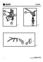
2-7 SAFETY DEVICES FITTED
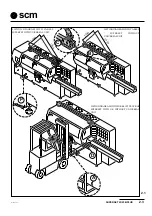
This machine has been built to provide maximum safety along with top performance. The machine features:
1) Shaving-conveyor guards on all heads.
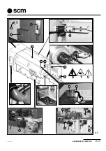
2) Pivoting hood (D fig. 2.7)
3) Emergency button on control panel (E fig. 2.7)
4) Emergency button at machine outfeed (F fig. 2.7)
5)
Mid-machine emergency button (G fig. 2.7)
6)
Infeed tunnel (A fig. 2.7)
7) Infeed bar with feed stop function in case of off-size thickness pieces (A1 fig.2.7)
8)
Outfeed tunnel (B fig. 2.7) with relative bar; this allows outfeed of machined piece only, and opening
from outside is prevented.
9)
Power interlock and mechanical locking of door for closing machine by means of electromagnet (C fig.
2.7) and positive control microswitch (Q fig. 2.7)
These prevent opening during machining. (The hood can only be opened with selector switch in manual
position (
), whenever adjustments have to be made) (Electromagnetic release is controlled by a timer)
In the event of a power interruption, the hood can only be opened by operating the interlock manually.
Introduce a 5 mm Allen wrench (L fig. 2.7) in the red socket head screw and rotate until the pin goes back
in.
10)
Protection devices (H fig. 2.7) on the control screws prevent the cranks remaining connected after
adjustments have been made.
11)
Guards (M fig. 2.7) positioned in front of the vertical heads.
12)
Self-braking motors on the heads.
13)
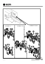
Filter unit and air reducing valve (N fig. 2.7) with padlockable stopcock and automatic air release.
14) Hand control unit (O fig. 2.7)
15)
All doors are closed with screws (P fig. 2.7)
16)
Piece feed wheel speed limiting device; microswitch (R fig.2.7) prevents feed speeds of over 15 m/ min.
in manual mode (
).
17)
Extraction pipe bend (90°) (V fig. 2.7) to be fitted to the extraction hood of the universal spindle.
Prevents chippings or pieces being machined from accidentally piercing the extraction hose (W fig. 2.7)
18) “Unit not operating” control devices (Limit switch X fig. 2.7).
The device is fitted on units:
2nd right vertical, layouts 13-14-17-18.
2nd lower horizontal, layouts 5-6-13-14-15-16-17-18
2nd upper horizontal, layouts 15-16-17-18
Forward drive operates if:
-
units operating ( limit switch on and contact open) and switched on.
-
units not operating (limit switch off and contact closed) and switched off.
19) Danger indication plates (triangular with yellow background) fitted to various parts of the machine:
-
(S) electric power hazard
-
(T) danger from moving parts
-
(U) dangerous access to moving parts
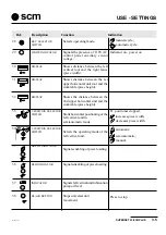
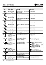
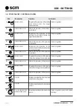
20) The safety devices used on the control panel are described in chapter 3.
It is up to the operator to periodically inspect the above devices to ensure they are working correctly.
Any faults should be notified immediately to the person in charge.
Summary of Contents for Superset 23
Page 2: ...VUOTO AI ...
Page 25: ...SUPERSET 23 23E PLUS 2 5 ad i2 pm5 P5 scm 2 2 PE L2 L3 L1 N COM2 3 125 007 Ec 0 G G ...
Page 27: ...SUPERSET 23 23E PLUS 2 7 ad i2 pm5 P7 scm 2 5 N L 125 012 Ez 0 U U 2 4 N ...
Page 32: ...INSTALLATION 2 12 SUPERSET 23 23E PLUS ad i2 pm5 P12 scm ...
Page 45: ...HEADS SUPERSET 23 23E PLUS 4 3 ad i4_1 P3 scm D L C M 4 1 A 4 1a 4 1b max 1 5mm min 22mm T Z ...
Page 51: ...HEADS SUPERSET 23 23E PLUS 4 9 ad i4_2 P9 scm 4 5 4 4 A D C B S SUP310 SUP311_L V ...
Page 57: ...HEADS SUPERSET 23 23E PLUS 4 15 ad i4_2 P15 scm 4 10 3 18 D 7 5 4 6 ...
Page 61: ...HEADS SUPERSET 23 23E PLUS 4 19 ad i4_3 P19 scm 4 13 4 14 L H G H SUP325_L SUP326_L I A S D M ...
Page 65: ...HEADS SUPERSET 23 23E PLUS 4 23 ad i4_3 P23 scm SUP353_L A 4 17 ...
Page 67: ...HEADS SUPERSET 23 23E PLUS 4 25 ad i4_3 P25 scm SUP312_L F G 4 20 SUP342_L Y I X K L N 4 19 ...
Page 71: ...HEADS SUPERSET 23 23E PLUS 4 29 ad i4_3 P29 scm 4 24 G U V I ...
Page 73: ...HEADS SUPERSET 23 23E PLUS 4 31 ad i4_3 P31 scm 4 26 4 27 F M T G B ...
Page 76: ...HEADS 4 34 SUPERSET 23 23E PLUS ad i4_3 P34 scm ...
Page 79: ...OPTIONAL UNITS SUPERSET 23 23E PLUS 10 3 ad i10_1 P3 scm 10 4 B C A SUP359_L 10 3 K SUP347 ...
Page 85: ...OPTIONAL UNITS SUPERSET 23 23E PLUS 10 9 ad i10_1 P9 scm SUP3331_L 10 10 E D X ...
Page 93: ...OPTIONAL UNITS SUPERSET 23 23E PLUS 10 17 ad i10_1 P17 scm 10 20 10 21 SUP321 SUP3 20 V L P ...
Page 95: ...OPTIONAL UNITS SUPERSET 23 23E PLUS 10 19 ad i10_2 P19 scm 10 22 E C D A B SUP327_L ...
Page 97: ...OPTIONAL UNITS SUPERSET 23 23E PLUS 10 21 ad i10_2 P21 scm 10 23 L N M G F H SUP328_L ...
Page 99: ...OPTIONAL UNITS SUPERSET 23 23E PLUS 10 23 ad i10_2 P23 scm 10 25 sup327_l T S E F D ...
Page 101: ...OPTIONAL UNITS SUPERSET 23 23E PLUS 10 25 ad i10_2 P25 scm 10 26 SUP331_L Y W X Z R U V ...
Page 103: ...OPTIONAL UNITS SUPERSET 23 23E PLUS 10 27 ad i10_2 P27 scm 10 28 M N G F U ...
Page 107: ...OPTIONAL UNITS SUPERSET 23 23E PLUS 10 31 ad i10_2 P31 scm 10 32 R A U H F W C D B K E ...
Page 108: ...OPTIONAL UNITS 10 32 SUPERSET 23 23E PLUS ad i10_2 P32 scm ...
Page 109: ...SUPERSET 23 23E PLUS 19 1 19 SECTION 19 SELF BRAKING MOTOR ...
Page 111: ...SUPERSET 23 23E PLUS 19 3 19 19 1 19 2 freno1 freno2 ...
Page 112: ...SELF BRAKING MOTOR 19 4 SUPERSET 23 23E PLUS SEZ I19 ...
Page 115: ...MAINTENANCE SUPERSET 23 23E PLUS 20 3 ad i20_1 P3 scm 20 3 7 1 3 2 4 5 G 6 20 2 20 1 ...
Page 129: ...MAINTENANCE SUPERSET 23 23E PLUS 20 17 ad i20_2 pm5 P17 scm 20 20 S U P 4 2 2 _ M A ...
Page 136: ...APPENDIX A 2 SUPERSET 23 23E PLUS ad appen pm5 P2 scm ...
Page 137: ...SUPERSET 23 23E PLUS A 3 ad appen pm5 P3 scm APPENDIX ...
Page 138: ...APPENDIX A 4 SUPERSET 23 23E PLUS ad appen pm5 P4 scm ...
Page 139: ...SUPERSET 23 23E PLUS A 5 ad appen pm5 P5 scm APPENDIX ...
Page 140: ...APPENDIX A 6 SUPERSET 23 23E PLUS ad appen pm5 P6 scm ...
Page 141: ...SUPERSET 23 23E PLUS A 7 ad appen pm5 P7 scm APPENDIX ...
Page 142: ...APPENDIX A 8 SUPERSET 23 23E PLUS ad appen pm5 P8 scm ...
Page 143: ...SUPERSET 23 23E PLUS A 9 ad appen pm5 P9 scm APPENDIX ...
Page 144: ...APPENDIX A 10 SUPERSET 23 23E PLUS ad appen pm5 P10 scm ...
Page 145: ...SUPERSET 23 23E PLUS A 11 ad appen pm5 P11 scm APPENDIX ...

