USE - SETTINGS
3.10
SUPERSET 23/23E/PLUS
ad-i3.pm5 P10
scm
3-7 SELF-BRAKING MOTOR
The spindle is turned by an electric self-braking motor.
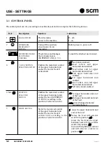
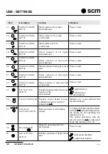
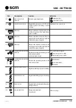
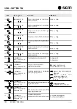
In normal conditions, the selector switch (25 § 3.1) is in left position
When turning off the power supply by turning the spindle control switches to 0, or pressing button
, the motor
automatically brakes and remains braked until it is started up again.
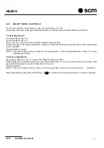
If adjustments have to be made, such as fitting of planes, etc., where the spindle has to turn freely, turn the selector
switch (25) to the right position
. The indicator light (24) will come on at the same time In these conditions,
the machine cannot be started and consequently adjustments can be made in perfect safety.
The motor can be started only if the selector switch (25) is turned to the left
With the heads on, by turning the selector switch (25) from position
to position
the units switch off,
the brake is triggered and, if running, the feed stops.
The brakes of the heads are released after 20 seconds.
NOTE: The materials used in the self-braking motors for quick tool stop do not contain carcinogenic substances.
3-8 MODE SELECTOR SWITCH OPERATION
The mode selector switch is of the key type.
MANUAL MODE
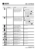
For manual mode, turn the switch (28 § 3.1) to position (
)
In manual mode:
1) The hood can be opened after 20 sec.
2) The feed only jog operates, (only if set at a speed below or equal to 15 m/min), forward if the heads are on,
in reverse only if the heads are off.
3) In case of stop of heads by means of single button
(26 § 3.1
), the motor brakes are operated.
4) Emergencies always active (2 § 3.1)
AUTOMATIC MODE
For manual mode, turn the selector switch (28 §3.1) to position
In manual mode:
1) The hood is blocked by means of an electromagnet.
2) Continuous feed operation, if the first four heads (lower horizontal, right vertical, left vertical, upper
horizontal) are on, and the remaining heads (2nd lower horizontal, 2nd right vertical, 2nd upper horizontal),
depending on layout, are on in work position, or off in non-work position (indicated by a limit switch).
3) In case of stop of heads by means of single button
(26 § 3.1
) the motor brakes are not operated.
4) Passing from automatic to manual mode with units on, these switch off and the motor brakes are operated.
5) Emergencies always active (2 § 3.1)
Summary of Contents for Superset 23
Page 2: ...VUOTO AI ...
Page 25: ...SUPERSET 23 23E PLUS 2 5 ad i2 pm5 P5 scm 2 2 PE L2 L3 L1 N COM2 3 125 007 Ec 0 G G ...
Page 27: ...SUPERSET 23 23E PLUS 2 7 ad i2 pm5 P7 scm 2 5 N L 125 012 Ez 0 U U 2 4 N ...
Page 32: ...INSTALLATION 2 12 SUPERSET 23 23E PLUS ad i2 pm5 P12 scm ...
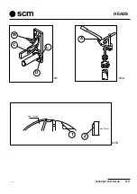
Page 45: ...HEADS SUPERSET 23 23E PLUS 4 3 ad i4_1 P3 scm D L C M 4 1 A 4 1a 4 1b max 1 5mm min 22mm T Z ...
Page 51: ...HEADS SUPERSET 23 23E PLUS 4 9 ad i4_2 P9 scm 4 5 4 4 A D C B S SUP310 SUP311_L V ...
Page 57: ...HEADS SUPERSET 23 23E PLUS 4 15 ad i4_2 P15 scm 4 10 3 18 D 7 5 4 6 ...
Page 61: ...HEADS SUPERSET 23 23E PLUS 4 19 ad i4_3 P19 scm 4 13 4 14 L H G H SUP325_L SUP326_L I A S D M ...
Page 65: ...HEADS SUPERSET 23 23E PLUS 4 23 ad i4_3 P23 scm SUP353_L A 4 17 ...
Page 67: ...HEADS SUPERSET 23 23E PLUS 4 25 ad i4_3 P25 scm SUP312_L F G 4 20 SUP342_L Y I X K L N 4 19 ...
Page 71: ...HEADS SUPERSET 23 23E PLUS 4 29 ad i4_3 P29 scm 4 24 G U V I ...
Page 73: ...HEADS SUPERSET 23 23E PLUS 4 31 ad i4_3 P31 scm 4 26 4 27 F M T G B ...
Page 76: ...HEADS 4 34 SUPERSET 23 23E PLUS ad i4_3 P34 scm ...
Page 79: ...OPTIONAL UNITS SUPERSET 23 23E PLUS 10 3 ad i10_1 P3 scm 10 4 B C A SUP359_L 10 3 K SUP347 ...
Page 85: ...OPTIONAL UNITS SUPERSET 23 23E PLUS 10 9 ad i10_1 P9 scm SUP3331_L 10 10 E D X ...
Page 93: ...OPTIONAL UNITS SUPERSET 23 23E PLUS 10 17 ad i10_1 P17 scm 10 20 10 21 SUP321 SUP3 20 V L P ...
Page 95: ...OPTIONAL UNITS SUPERSET 23 23E PLUS 10 19 ad i10_2 P19 scm 10 22 E C D A B SUP327_L ...
Page 97: ...OPTIONAL UNITS SUPERSET 23 23E PLUS 10 21 ad i10_2 P21 scm 10 23 L N M G F H SUP328_L ...
Page 99: ...OPTIONAL UNITS SUPERSET 23 23E PLUS 10 23 ad i10_2 P23 scm 10 25 sup327_l T S E F D ...
Page 101: ...OPTIONAL UNITS SUPERSET 23 23E PLUS 10 25 ad i10_2 P25 scm 10 26 SUP331_L Y W X Z R U V ...
Page 103: ...OPTIONAL UNITS SUPERSET 23 23E PLUS 10 27 ad i10_2 P27 scm 10 28 M N G F U ...
Page 107: ...OPTIONAL UNITS SUPERSET 23 23E PLUS 10 31 ad i10_2 P31 scm 10 32 R A U H F W C D B K E ...
Page 108: ...OPTIONAL UNITS 10 32 SUPERSET 23 23E PLUS ad i10_2 P32 scm ...
Page 109: ...SUPERSET 23 23E PLUS 19 1 19 SECTION 19 SELF BRAKING MOTOR ...
Page 111: ...SUPERSET 23 23E PLUS 19 3 19 19 1 19 2 freno1 freno2 ...
Page 112: ...SELF BRAKING MOTOR 19 4 SUPERSET 23 23E PLUS SEZ I19 ...
Page 115: ...MAINTENANCE SUPERSET 23 23E PLUS 20 3 ad i20_1 P3 scm 20 3 7 1 3 2 4 5 G 6 20 2 20 1 ...
Page 129: ...MAINTENANCE SUPERSET 23 23E PLUS 20 17 ad i20_2 pm5 P17 scm 20 20 S U P 4 2 2 _ M A ...
Page 136: ...APPENDIX A 2 SUPERSET 23 23E PLUS ad appen pm5 P2 scm ...
Page 137: ...SUPERSET 23 23E PLUS A 3 ad appen pm5 P3 scm APPENDIX ...
Page 138: ...APPENDIX A 4 SUPERSET 23 23E PLUS ad appen pm5 P4 scm ...
Page 139: ...SUPERSET 23 23E PLUS A 5 ad appen pm5 P5 scm APPENDIX ...
Page 140: ...APPENDIX A 6 SUPERSET 23 23E PLUS ad appen pm5 P6 scm ...
Page 141: ...SUPERSET 23 23E PLUS A 7 ad appen pm5 P7 scm APPENDIX ...
Page 142: ...APPENDIX A 8 SUPERSET 23 23E PLUS ad appen pm5 P8 scm ...
Page 143: ...SUPERSET 23 23E PLUS A 9 ad appen pm5 P9 scm APPENDIX ...
Page 144: ...APPENDIX A 10 SUPERSET 23 23E PLUS ad appen pm5 P10 scm ...
Page 145: ...SUPERSET 23 23E PLUS A 11 ad appen pm5 P11 scm APPENDIX ...

