HEADS
4.2
SUPERSET 23/23E/PLUS
ad-i4_1 P2
scm
4-1 TOOL ADJUSTMENT AND SPINDLE CLAMPING
Whenever the tools have to be adjusted, all the parts making up the planes will have to be carefully dismantled
and cleaned with non-dangerous solvent, one at a time, taking care not to swap the parts around so as not to create
unbalance. Refit the blades and the gibs and make sure these do not jut out from the side of the plane body. For
planes in contact with shavers, see NOTE. Also make sure the blades are fully inserted in the plane.
The blade-adjusting device (OPTIONAL) must be fixed in such a position for the spindle to be horizontal.
Make sure this device is fitted in a clean and dust-free place.
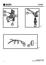
Loosen handle (M fig. 4.1) and raise angle bar (C) in order to fit the plane on the spindle so pin (D) engages a
slot between the gib and blade head.
Subsequently lower the angle bar until this is square with ring (L) to obtain an ideal 1÷1.5 mm projection of the
cutting edges; the result is a circle formed by the cutting edges with a diameter of 140 mm.
Finally, tighten the handle (M).
Using the tool provided (in the accessory pack), loosen screws (T fig. 4.1b), fastened in the body, thereby freeing
the blade which, pressed upwards by the springs, will rest against the surface of the blade-adjusting device (C
fig. 4.1).
Lightly tighten the screws (T fig. 4.1b).
Subsequently tighten the screws well, starting with those in the middle and going on to the others
alternatively.
N.B.:
The blade can protrude by a maximum 1.5 mm from the spindle body (fig. 4.1b)
The blades (Z fig. 4.1b) can be used up to a minimum height of 22 mm.
NOTE: In the case of machines with shavers, take care the blades intersect perfectly with the cutter. To position
the plane blades it is better to first of all fit the shaver and then theblades which must protrude from
the plane body towards the shaver by 2 mm.
Always make sure contact surfaces are perfectly clean before adjusting the blades.
The tool supporting surfaces must always be clean. The clamping and release of the screws which clamp the plane
on the spindle is easily done by means of tool (A) supplied with the machine (see fig. 4.1a).
Removing and fitting a blade when the plane is clamped to the spindle is never recommended. For best blade use
and to reduce sharpening as much as possible, the planes of the vertical and horizontal spindles can be swapped
over.
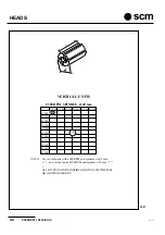
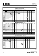
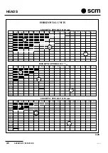
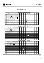
Figures 4.2, 4.2a, 4.2b and 4.2c show the tables, with a graph of possible solutions between tool diameter and
tool length, with reference to spindle rotation speed and the material of which the tool is made.
For tools with aluminium body, the solutions of areas (1) and (2) of the graph are possible. For tools with steel
body, use the indications of area (1) of the graph only. Any combination falling within area (3) cannot be used.
Important!!! The tools must always be positioned starting from the side near the bearing.
Summary of Contents for Superset 23
Page 2: ...VUOTO AI ...
Page 25: ...SUPERSET 23 23E PLUS 2 5 ad i2 pm5 P5 scm 2 2 PE L2 L3 L1 N COM2 3 125 007 Ec 0 G G ...
Page 27: ...SUPERSET 23 23E PLUS 2 7 ad i2 pm5 P7 scm 2 5 N L 125 012 Ez 0 U U 2 4 N ...
Page 32: ...INSTALLATION 2 12 SUPERSET 23 23E PLUS ad i2 pm5 P12 scm ...
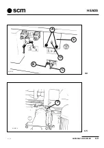
Page 45: ...HEADS SUPERSET 23 23E PLUS 4 3 ad i4_1 P3 scm D L C M 4 1 A 4 1a 4 1b max 1 5mm min 22mm T Z ...
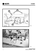
Page 51: ...HEADS SUPERSET 23 23E PLUS 4 9 ad i4_2 P9 scm 4 5 4 4 A D C B S SUP310 SUP311_L V ...
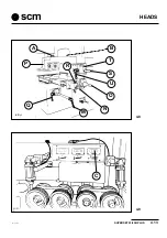
Page 57: ...HEADS SUPERSET 23 23E PLUS 4 15 ad i4_2 P15 scm 4 10 3 18 D 7 5 4 6 ...
Page 61: ...HEADS SUPERSET 23 23E PLUS 4 19 ad i4_3 P19 scm 4 13 4 14 L H G H SUP325_L SUP326_L I A S D M ...
Page 65: ...HEADS SUPERSET 23 23E PLUS 4 23 ad i4_3 P23 scm SUP353_L A 4 17 ...
Page 67: ...HEADS SUPERSET 23 23E PLUS 4 25 ad i4_3 P25 scm SUP312_L F G 4 20 SUP342_L Y I X K L N 4 19 ...
Page 71: ...HEADS SUPERSET 23 23E PLUS 4 29 ad i4_3 P29 scm 4 24 G U V I ...
Page 73: ...HEADS SUPERSET 23 23E PLUS 4 31 ad i4_3 P31 scm 4 26 4 27 F M T G B ...
Page 76: ...HEADS 4 34 SUPERSET 23 23E PLUS ad i4_3 P34 scm ...
Page 79: ...OPTIONAL UNITS SUPERSET 23 23E PLUS 10 3 ad i10_1 P3 scm 10 4 B C A SUP359_L 10 3 K SUP347 ...
Page 85: ...OPTIONAL UNITS SUPERSET 23 23E PLUS 10 9 ad i10_1 P9 scm SUP3331_L 10 10 E D X ...
Page 93: ...OPTIONAL UNITS SUPERSET 23 23E PLUS 10 17 ad i10_1 P17 scm 10 20 10 21 SUP321 SUP3 20 V L P ...
Page 95: ...OPTIONAL UNITS SUPERSET 23 23E PLUS 10 19 ad i10_2 P19 scm 10 22 E C D A B SUP327_L ...
Page 97: ...OPTIONAL UNITS SUPERSET 23 23E PLUS 10 21 ad i10_2 P21 scm 10 23 L N M G F H SUP328_L ...
Page 99: ...OPTIONAL UNITS SUPERSET 23 23E PLUS 10 23 ad i10_2 P23 scm 10 25 sup327_l T S E F D ...
Page 101: ...OPTIONAL UNITS SUPERSET 23 23E PLUS 10 25 ad i10_2 P25 scm 10 26 SUP331_L Y W X Z R U V ...
Page 103: ...OPTIONAL UNITS SUPERSET 23 23E PLUS 10 27 ad i10_2 P27 scm 10 28 M N G F U ...
Page 107: ...OPTIONAL UNITS SUPERSET 23 23E PLUS 10 31 ad i10_2 P31 scm 10 32 R A U H F W C D B K E ...
Page 108: ...OPTIONAL UNITS 10 32 SUPERSET 23 23E PLUS ad i10_2 P32 scm ...
Page 109: ...SUPERSET 23 23E PLUS 19 1 19 SECTION 19 SELF BRAKING MOTOR ...
Page 111: ...SUPERSET 23 23E PLUS 19 3 19 19 1 19 2 freno1 freno2 ...
Page 112: ...SELF BRAKING MOTOR 19 4 SUPERSET 23 23E PLUS SEZ I19 ...
Page 115: ...MAINTENANCE SUPERSET 23 23E PLUS 20 3 ad i20_1 P3 scm 20 3 7 1 3 2 4 5 G 6 20 2 20 1 ...
Page 129: ...MAINTENANCE SUPERSET 23 23E PLUS 20 17 ad i20_2 pm5 P17 scm 20 20 S U P 4 2 2 _ M A ...
Page 136: ...APPENDIX A 2 SUPERSET 23 23E PLUS ad appen pm5 P2 scm ...
Page 137: ...SUPERSET 23 23E PLUS A 3 ad appen pm5 P3 scm APPENDIX ...
Page 138: ...APPENDIX A 4 SUPERSET 23 23E PLUS ad appen pm5 P4 scm ...
Page 139: ...SUPERSET 23 23E PLUS A 5 ad appen pm5 P5 scm APPENDIX ...
Page 140: ...APPENDIX A 6 SUPERSET 23 23E PLUS ad appen pm5 P6 scm ...
Page 141: ...SUPERSET 23 23E PLUS A 7 ad appen pm5 P7 scm APPENDIX ...
Page 142: ...APPENDIX A 8 SUPERSET 23 23E PLUS ad appen pm5 P8 scm ...
Page 143: ...SUPERSET 23 23E PLUS A 9 ad appen pm5 P9 scm APPENDIX ...
Page 144: ...APPENDIX A 10 SUPERSET 23 23E PLUS ad appen pm5 P10 scm ...
Page 145: ...SUPERSET 23 23E PLUS A 11 ad appen pm5 P11 scm APPENDIX ...

