19.6
Cnusa19
SUPERSET XL
AUTO-BRAKING MOTOR
19-3 “LAFERT” AUTO-BRAKING MOTOR
MAINTENANCE
All interventions must always be carried out disconnecting the power line which feeds the motor and the brake.
For this operation, act on the main switch located on the electric panel.
REGULAR MAINTENANCE
Remove the fan cover hood (Part 17) by unscrewing the self-tapping screws.
With compressed air remove dust, wood shavings or other particles which have deposited on the brake system
and on the motor body.
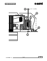
Insert a thickness gauge between part 43 (electromagnet) and part 37 (mobile core).
Check that there is an air space (air gap) of between 0.4 and 0.6 mm around the entire circumference.
If the air gap value reaches 0.8 mm there is no mechanical braking. Thus, the air gap will have to be reset and
the brake disk replaced (cooling fan) part 36.
For safety reasons, it is recommended the reset the air gap at an intermediate value between the limits indicated
above.
RESETTING THE AIR GAP
Having removed the fan cover hood (part 17), straighten the twisted tab of the safety washer (part 57) with a
metallic point.
With a tool, screw the ring nut (part 58) as much as necessary so that the air gap (distance at point TR), measured
with a thickness gauge, is reset to a minimum value of 0.4 mm on one side and to a maximum of 0.6 mm on the
opposite side.
Make a notch of the ring nut (part 58) coincide with a tab of the safety washer (part 57) by slightly screwing or
unscrewing the ring nut (part 58), and bending the tab to where it originally was.
Having rechecked the air gap, remount the external protection hood (part 17), and after reactivating the electric
panel, check proper functioning by starting and stopping the machine.
REPLACEMENT OF FAN WITH FRICTION DISK
Lift the tab of the safety washer, as for air gap resetting, and after completely unscrewing the ring nut (part 58)
and removing the safety washer (part 57), axially remove the fan (part 36) from the gear housing.
Having replaced the fan with a new one, first re-insert the washer (part 57), then the ring nut screwing it until
resetting the air gap as previously described.
It is recommended to carry out the fan replacement operation with the motor placed on a work bench and with
the spindle turned towards the bottom to prevent the springs (part 38) from falling out.
N.B.
a)
For electrical repairs it is recommended to contact an authorised LAFERT dealer or the
machine manufacturer
b)
The electrical connections of the motor and the brake must be carried out according to the
diagrams supplied.
Summary of Contents for SUPERSET XL
Page 18: ...2 3 SUPERSET XL INSTALLATION cnusa2 max 90 1 2 0 0 m m 1 4 0 0 m m B C A P 2 1 ...
Page 20: ...2 5 SUPERSET XL INSTALLATION cnusa2 L2 L3 L1 PE Ref G 2 2 ...
Page 22: ...2 7 SUPERSET XL INSTALLATION cnusa2 2 3 L L2 N D C L2 L N D C ...
Page 24: ...2 9 SUPERSET XL INSTALLATION cnusa2 E 2 4 A 2 4a B ...
Page 26: ...2 11 SUPERSET XL INSTALLATION cnusa2 D E F A Q M CAUTION CAUTION CAUTION K H G S T U ...
Page 29: ...2 14 cnusa2 SUPERSET XL INSTALLATION ...
Page 48: ...4 7 SUPERSET XL cnci4 OPERATING UNITS H C 4 4 S V X G B 4 3 4 5 16 ...
Page 56: ...4 15 SUPERSET XL cnci4 OPERATING UNITS B 4 17 4 18 M C E D A Q Q 16 F ...
Page 58: ...4 17 SUPERSET XL cnci4 OPERATING UNITS 4 19 A B R P M C 4 19a 4 19b 4 19c M D E X ...
Page 60: ...4 19 SUPERSET XL cnci4 OPERATING UNITS 4 20 P M T G ...
Page 64: ...4 23 SUPERSET XL cncgb4_1 OPERATING UNITS S B Z C E E1 A M X R D E2 V K2 K1 J K1 ...
Page 66: ...4 25 SUPERSET XL cncgb4_1 OPERATING UNITS B Z C A M E R V K2 K1 G2 ...
Page 68: ...4 27 SUPERSET XL cncgb4_1 OPERATING UNITS E D D V K2 K1 G2 X1 W1 B Z C A M ...
Page 70: ...4 29 SUPERSET XL cncgb4_1 OPERATING UNITS B Z C A M D D K2 K1 G2 X1 W1 E E W1 V1 U P Y U ...
Page 73: ...4 32 cncgb4_1 SUPERSET XL OPERATING UNITS ...
Page 78: ...10 5 SUPERSET XL Cnusa10 ADJUSTMENT AND USE OF OPTIONAL UNITS B A P 10 3 ...
Page 82: ...10 9 SUPERSET XL Cnusa10 ADJUSTMENT AND USE OF OPTIONAL UNITS 10 7 10 8 N A V T R ...
Page 90: ...10 17 SUPERSET XL Cnusa10 ADJUSTMENT AND USE OF OPTIONAL UNITS 10 15 10 16 D B C E F G H L V ...
Page 98: ...10 25 SUPERSET XL Cnusa10 ADJUSTMENT AND USE OF OPTIONAL UNITS T P ...
Page 99: ...10 26 SUPERSET XL Cnusa10 ADJUSTMENT AND USE OF OPTIONAL UNITS ...
Page 102: ...19 3 SUPERSET XL Cnusa19 AUTO BRAKING MOTOR A B C ...
Page 104: ...19 5 SUPERSET XL Cnusa19 AUTO BRAKING MOTOR A B F C P D ...
Page 107: ...19 8 Cnusa19 SUPERSET XL AUTO BRAKING MOTOR ...
Page 110: ...20 3 SUPERSET XL MAINTENANCE Cnnci20 20 1 ...
Page 112: ...20 5 SUPERSET XL MAINTENANCE Cnnci20 R L S 20 2 20 3 V T 20 2a G ...
Page 114: ...20 7 SUPERSET XL MAINTENANCE Cnnci20 20 4 A M N K F 20 5 B 20 6 20 6a C M N ...
Page 116: ...20 9 SUPERSET XL MAINTENANCE Cnnci20 K F 20 7 20 7a 20 7b D E M N P Q R ...


